
FIG. 01
RECORD DATA
Category
Electronics
TARİH
Our battery supplier's list has fifteen different packs on it: "6S 10000mAh 25C", "6S 16000mAh 15C", "4S 5200mAh 75C". Every one has a different price and a different weight, and not one of them comes with a note saying "this is the right pack for your aircraft." Before our first order, we sat frozen in front of exactly that screen.
Then we ran into two separate problems in the field. First: the instant the motors went to full throttle the voltage collapsed and tripped the flight controller's low-voltage failsafe — the battery wasn't empty, it just couldn't deliver the current. Second: we bought a bigger pack expecting to double our flight time, and the increase we actually got wasn't even half of that.
In this post we reduce battery selection to three numbers: cell count sets voltage, capacity sets energy, and C-rate sets current. All three can be chosen by calculation, and all three should be. At the end we cover the safety side without glossing over it, because a mistake with LiPo usually comes back as a fire.
Cell count (S) and voltage
LiPo (lithium polymer) packs are built by wiring individual cells in series. The "6S" on the label tells you six cells are connected in series. A LiPo cell has a nominal voltage of 3.7 V and sits at 4.2 V fully charged. High-voltage cells (LiHV) push that ceiling to 4.35 V and the nominal figure to 3.8 V — but charging a standard LiPo to 4.35 V wrecks the chemistry and is dangerous, so never run the two types on the same charge profile.
State | Per cell | 4S | 6S |
|---|---|---|---|
Fully charged | 4.20 V | 16.8 V | 25.2 V |
Nominal (the label value) | 3.70 V | 14.8 V | 22.2 V |
Storage target | ~3.80 V | 15.2 V | 22.8 V |
Practical floor (under load) | ~3.50 V | 14.0 V | 21.0 V |
Absolute floor | 3.00 V | 12.0 V | 18.0 V |
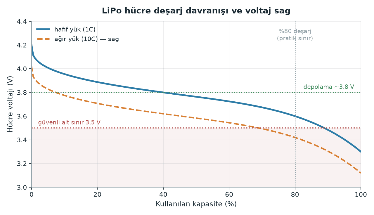
We put the practical floor at 3.5 V because draining a cell down to 3.0 V shortens its life fast, and voltage falls off a cliff in that last twenty percent. Common practice in the multirotor community is to set the warning at ~3.5 V per cell and the forced landing at ~3.2 V. The ArduPilot documentation leaves the values up to the user, but don't forget that the BATT_LOW_VOLT default is 10.5 V — sized for 3S. On a 6S aircraft, if you leave that parameter alone the failsafe will never fire.
BATT_FS_VOLTSRC matters in particular: if you make the decision on raw voltage, every hard maneuver trips the failsafe.
What does capacity (mAh) actually measure?
Capacity is given in milliamp-hours: 10000 mAh = 10 Ah, so in theory the pack can supply 10 A for one hour. But to compare packs with different cell counts you need energy, not capacity.
Energy (Wh) = nominal voltage (V) × capacity (Ah)
Pack | Energy |
|---|---|
6S 10000 mAh | 22.2 V × 10 Ah = 222 Wh |
4S 5200 mAh | 14.8 V × 5.2 Ah = 77 Wh |
That number isn't just academic: air travel rules define their thresholds in watt-hours. Packs under 100 Wh are fine in carry-on baggage on a passenger flight, 100-160 Wh needs airline approval, and anything over 160 Wh is prohibited (IATA/FAA, as of 2026). At 222 Wh, the 6S 10000 mAh pack above lands squarely in the prohibited class — if you're flying to the competition, plan for this months before the trip.
C-rate: the current on the label vs. the current you can actually draw
C-rate tells you how fast a pack can discharge relative to its capacity. The formula is simple:
Maximum continuous current (A) = C-rate × capacity (Ah)
Pack | Maximum continuous current |
|---|---|
6S 10000 mAh 25C | 25 × 10 = 250 A |
4S 5200 mAh 75C | 75 × 5.2 = 390 A |
6S 16000 mAh 15C | 15 × 16 = 240 A |
Here's the trap: C on its own is meaningless — it always has to be multiplied by capacity. The small pack labeled "75C" can push more current than the big pack labeled "15C" — but it's empty in three minutes.
The second trap is that most labels are marketing numbers. Packs usually carry two figures: continuous and burst (typically rated over 5-10 seconds). Independent testers report that the continuous C figure printed on the label isn't actually sustainable, and that the real continuous current sits well below the label value. Our approach: the highest current the aircraft draws continuously should never exceed half the label's continuous figure. So on a pack rated 250 A, we treat 120 A as the ceiling.
The way to estimate your aircraft's real current draw is the motor manufacturer's thrust data. The amp figures are listed there for each motor + propeller + cell count combination; on a quad, multiply that value by four and add the draw of the camera/gimbal and the companion computer. We covered the power profile of a board like the Jetson Orin NX in our Jetson setup post; it's small next to the motors, but it still belongs in the budget.
Internal resistance and voltage sag
A battery is not an ideal voltage source; every cell has an internal resistance (IR), and as current flows you lose voltage across it. Ohm's law:
V_sag=I×R_total
R_total= cell count × per-cell IR
P_heat=I^2×R_total
Example: a 6S pack at 3 mΩ per cell, at a 100 A draw.
Quantity | Worked value |
|---|---|
| 6 × 0.003 = 0.018 Ω |
| 100 × 0.018 = 1.8 V |
Voltage under load (full pack 25.2 V) | 23.4 V |
| 100^2 × 0.018 = 180 W |
That was the answer to our first problem: the pack wasn't empty, its internal resistance was simply dragging it below the failsafe threshold under load. IR climbs with age and cycle count. A fresh pack measuring a few milliohms per cell can be several times that after hundreds of cycles; at that point it both sags early and heats up dangerously. A good charger measures IR per cell — write that number down on the pack's first day and make it your reference.
Estimating flight time and the weight trade-off
Flight time (min) = [ capacity (Ah) × usable fraction ] / average current (A) × 60
usable fraction: assume 0.8 (don't use the last 20% of the pack)
Example: a 6S 10000 mAh pack on an aircraft we measured at 35 A in hover.
(10 Ah × 0.8) / 35 A = 0.229 hours = 13.7 minutes
Now let's test the "twice the battery, twice the endurance" assumption. Our aircraft weighs 4.0 kg (1.0 kg of that is battery). Going up to 20000 mAh makes the pack ~2.0 kg and pushes takeoff weight to 5.0 kg. By momentum theory, hover power scales with weight to the 1.5 power:
I_new= 35 A × (5.0 / 4.0)^1.5 = 35 × 1.40 = 48.9 ATime = (20 × 0.8) / 48.9 × 60 = 19.6 minutes
We raised capacity by 100% and flight time by 43%. This is a simplified model — efficiency losses and a propeller change aren't accounted for — but it points in the right direction: the bigger the battery, the smaller the return, and past a certain point flight time stops rising and starts falling. The right method is to run several weight scenarios through the motor thrust table and find the peak of the curve.
Series and parallel wiring
The notation reads like "6S2P": six cells in series, two of those strings in parallel.
Wiring | Voltage | Capacity | Continuous current | When to use |
|---|---|---|---|---|
Series (S) | Adds up | Unchanged | Unchanged | When the motors/ESCs want higher voltage; less current for the same power, so thinner wiring |
Parallel (P) | Unchanged | Adds up | Adds up | When you need flight time and current headroom; two mid-size packs instead of one big one |
Parallel wiring comes with strict rules: the packs must have the same cell count, the same capacity, the same C rating and, if possible, the same age. Before you connect them, the voltage difference between packs has to be under 0.05 V per cell — otherwise the fuller pack dumps a massive current into the emptier one the moment they touch. Flying two packs of different ages in parallel means the older one is permanently overloaded.
The Li-ion alternative
Fixed-wing and VTOL projects that need long endurance tend to reach for cylindrical Li-ion cells (18650/21700). The difference comes down to the trade-off between energy density and current capability:
LiPo (pouch) | Li-ion (cylindrical) | |
|---|---|---|
Energy density | Lower | Higher |
Continuous C | High (tens of C) | Low (typically a few C) |
Form factor | Thin, flexible packaging | Fixed cylinder, airframe has to be designed around it |
When to use | Multirotor, high thrust margin, aggressive maneuvering | Long range/endurance, low and steady current profile |
A concrete example: the Molicel INR-21700-P45B is a "power" Li-ion cell with 4.5 Ah capacity at 3.6 V nominal (16.2 Wh), and the manufacturer rates continuous discharge at 45 A — roughly 10C. Energy-oriented Li-ion cells give you more capacity but far lower continuous current. Whichever cell you pick, don't guess its C rating: look up the continuous discharge current on the manufacturer's datasheet and divide your total current requirement by the number of cells in parallel.
For multirotors, our general advice is to stay with LiPo. Hover current is high, and sizing a Li-ion pack large enough to deliver it eats up the energy-density advantage entirely.
Safety: no shortcuts here
Charge current. The default is 1C (10 A for a 10000 mAh pack). Some manufacturers allow 2-5C; that information lives on the pack's own datasheet, so don't guess. Fast charging shortens life.
Balance lead always connected. Balance charging evens the cells out. If you see a persistent difference of more than 0.05 V between cells, the pack is aging.
No unattended charging. Charge on a non-flammable surface, inside a LiPo bag or a metal/ceramic container. Keep flammable material away from it.
Don't charge a hot pack. After a flight, wait for it to come back down to room temperature.
Storage at ~3.8 V/cell. A pack left fully charged will puff. If it's going to sit for more than a day or two, use your charger's "storage" mode.
Swelling or physical damage = pack retired. Don't charge, fly or puncture a swollen pack. Take it to your local hazardous waste drop-off; never try to discharge a punctured or deformed pack yourself.
In case of fire. Once thermal runaway has started, don't focus on putting the pack out — focus on protecting what's around it: non-flammable surface, smother it with sand or cat litter, plenty of ventilation (the smoke is toxic). Have a plan and a bucket ready for this in advance.
Transport. Tape over the main connector, protect the balance plug, and never put packs in the same bag as metal objects.
Common pitfalls
Running a pack all the way down. Telemetry showing 0% at the end of a flight means you stole life from the pack. A 20% reserve is both safety and economics.
Reading the C rating independently of capacity. A 1300 mAh pack labeled "100C" delivers less current than a 10000 mAh pack labeled "25C". Always multiply.
Mistaking the burst figure for the continuous one. The big number on the label is usually burst. Look for the continuous figure, and if you can't find it, don't buy that pack.
Deciding on resting voltage. Voltage under load is always lower. Set your failsafe thresholds from the under-load voltage in the flight log, not from a bench measurement.
Leaving the failsafe parameters at their defaults. The BATT_LOW_VOLT default is sized for 3S. If you don't change it on a 6S aircraft, there is no protection.
Flying packs of different ages in parallel. The weaker pack is constantly overloaded, and it's the one that puffs first.
Practical summary
Pick current first, capacity second. Find your continuous current from the motor thrust table and treat half the label's C rating as your ceiling. If the current isn't there, capacity does you no good at all.
Run the three formulas once before you fly:
current = C × Ah,time = (Ah × 0.8) / I_avg × 60,V_sag = I × R. All three are one-liners, and all three save you from surprises in the field.Set the failsafe thresholds from the log. ~3.5 V per cell for the warning, ~3.2 V for the forced landing; turn on sag correction with
BATT_FS_VOLTSRC=1. Pairing the log-analysis habit with the telemetry stream from our companion computer post makes the job much easier.Number every pack and record its IR. The internal resistance you measure on day one is your reference; when it doubles, pull that pack out of mission flights.
Make storage voltage part of the routine. Outside competition week, no pack should sit fully charged; ~3.8 V/cell buys you both safety and service life.
We learned on our SUAS 2026 journey that the battery is not a line item to be "sorted out later." The power system determines from the outset how long the aircraft flies, how much it carries and which maneuvers it can pull off — it's a constraint you have to calculate before you choose a model or plan a mission.
