
FIG. 01
RECORD DATA
Category
Electronics
TARİH
Motor and ESC selection is the decision teams regret most on a multirotor build. The reason is simple: at the moment you choose, the only number in front of you is the "max thrust" figure from the product page, while the thing that actually matters in flight is an operating point far below it. The aircraft lifts off, it hovers, it even looks good — and then flight time comes in at half of what you calculated.
The second classic scenario is more expensive: everything runs fine for weeks, then on a windy day, during an aggressive maneuver, an ESC starts smoking. You open the log and hover current reads 2 A. "How does a 30 A ESC burn up?" Answer: because you sized it off hover current.
In this post we reduce motor and ESC selection to three concrete calculations — the KV/propeller trade-off, flight time from efficiency (g/W), and a current budget that runs from the motor all the way back to the battery. So that we are not inventing numbers, we will work the examples off a real manufacturer datasheet.
What KV actually tells you, and what it doesn't
KV (RPM/V, revolutions per volt) is the constant that describes how many turns a motor makes per volt with no load on it. That means a 300 KV motor can spin up to roughly 6900 RPM at 23 V — with no propeller fitted.
Real data is the best way to see the gap. T-Motor measured the MN5006 KV300 with a P17×5.8" prop at 5491 RPM on 6S at full throttle, 23.22 V. The unloaded expectation is ~6970 RPM, so it drops about 21% under load. KV is not a ceiling, it is a scaling factor: raising KV on the same motor body buys a tendency to spin faster and less torque.
Never read KV on its own — read it alongside three things: cell count (S), prop diameter/pitch, and stator size. Manufacturer motor names are usually the stator dimensions: "5006" ≈ 50 mm stator diameter, 6 mm stator height. The bigger the stator, the more copper and iron the motor carries; it makes more torque at the same current and runs cooler. Winding a high KV onto a small stator and bolting a big prop to it is buying heat and lost efficiency.
High KV with a small prop, or low KV with a big prop?
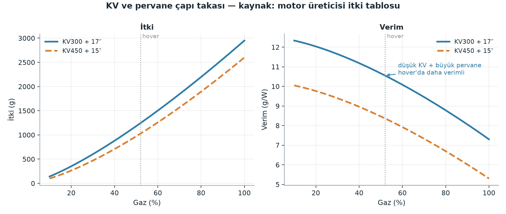
The cleanest example of this trade-off is two motors from the same manufacturer built on the same stator. The table below is 6S data for the two KV variants of the T-Motor MN5006, each on its own recommended prop (KV300 + P17×5.8", KV450 + P15×5"):
Measurement | KV300 + 17" | KV450 + 15" |
|---|---|---|
Thrust at 60% throttle | 1119 g | 1458 g |
Efficiency at 60% throttle | 10.18 g/W | 7.61 g/W |
Thrust at 100% | 2538 g | 3218 g |
Current at 100% | 15.41 A | 26.28 A |
Efficiency at 100% | 7.09 g/W | 5.35 g/W |
Peak current (180 s) | 20 A | 26 A |
Internal resistance | 125 mΩ | 60 mΩ |
Same stator, same weight class, same battery. The low KV + big prop package gives up about 21% of peak thrust and returns markedly higher g/W at the same throttle setting. This is a package-to-package comparison, not motor-to-motor — the prop changes too, and that is exactly the point.
Choice | When to pick it |
|---|---|
Low KV + big prop | Long endurance, heavy payload, steady mission flying. The default for autonomous mission aircraft. |
High KV + small prop | Fast acceleration, aggressive maneuvering, tight frame/prop clearance, high wind tolerance. |
Why efficiency (g/W) can matter more than the T/W ratio
Thrust-to-takeoff-weight ratio (T/W) is a measure of safety and control authority: an aircraft that drops below 2:1 does not have enough margin in wind or in a maneuver. But T/W says nothing about flight time. g/W does: how many grams you lift per watt burned.
The critical point is that g/W is not constant — it falls as throttle rises. In the KV300 data above, 40% throttle gives 13.02 g/W and 100% throttle gives 7.09 g/W. So every extra gram that forces your aircraft to fly up in the motors' peak range bills you twice: it draws more watts, and it spends each watt less efficiently.
Rule of thumb: your hover operating point should land in the lower-middle band of the datasheet, where efficiency is highest, not up at the top.
Hover thrust per motor =
Takeoff weight (g)/Motor countFlight time (min) ≈ (
Capacity_Ah×usable_fraction/Total_current_A) × 60
Example: a quad with a 2400 g takeoff weight, running the MN5006 KV300 + 17" package.
Hover thrust per motor = 2400 / 4 = 600 g
Datasheet (6S):
40% → 501 g @ 1.63 A
45% → 640 g @ 2.21 A
Interpolating for 600 g: 1.63 + (600-501)/(640-501) × (2.21-1.63) ≈ 2.04 A
Motor total in hover = 4 × 2.04 ≈ 8.2 A
Avionics load =
A_avi(MEASURE IT: companion computer, gimbal, telemetry, receiver)
Do not guess at A_avi; run the aircraft on the bench and read it off the power module. What a Jetson-class companion computer draws depends on the workload, so quoting a single number would be misleading. Say you measured it and got 2.0 A:
Total hover current = 8.2 + 2.0 = 10.2 A
6S 6.0 Ah pack, 80% usable capacity:
Flight time ≈ (6.0 × 0.80 / 10.2) × 60 ≈ 28 min (hover, no wind)
Treat that number as an upper bound. Wind, cruise speed and maneuvering all pull average current up; on a real mission flight, expect noticeably less.
Current budget: from the motor to the ESC to the battery
Hover current sets your flight time; peak current sets your hardware. Confusing the two is the burnt-ESC story from the top of this post.
Total peak current =
Motor peak current×Motor countESC continuous rating ≥
Motor peak current× 1.2 … 1.3 (20-30% margin)Required battery continuous current =
Total peak currentBattery continuous C =
Required current (A)/Capacity (Ah)
With the same example:
Motor peak current (datasheet, 180 s) = 20 A
Minimum ESC continuous rating = 20 × 1.3 = 26 A → pick 30 A or above
Total peak current = 20 × 4 = 80 A
Continuous C required for a 6.0 Ah pack = 80 / 6.0 ≈ 13.3C
Label C ratings are optimistic, so apply a 70% derate:
Label C to look for ≈ 13.3 / 0.7 ≈ 19C → a 20C or better pack
Do not take the label C rating on faith: the common observation in the industry is that packs realistically deliver around 60-70% of their labeled continuous current. The same logic applies to ESCs — an ESC's "peak" rating is usually a figure good for a few seconds, and the continuous rating is roughly 60-70% of it.
Safety warning: LiPo packs go into thermal runaway on a short circuit or under excessive current. Do not put a cold solder joint, undersized wire or a marginal connector anywhere on the high-current path (battery → PDB → ESC); those connections make resistance, and resistance makes heat. Run all current testing with the props removed and the aircraft physically secured.
The ESC side: protocols, BEC, and calibration
After the current rating, the second thing to check on an ESC is protocol support. In ArduPilot the protocol is selected with MOT_PWM_TYPE:
Protocol | MOT_PWM_TYPE | Notes |
|---|---|---|
Normal PWM | 0 | 1000-2000 µs, frame rate 50-490 Hz ( |
OneShot | 1 | Locked to the main loop rate. The ArduPilot documentation states it offers "little advantage" over plain PWM. |
OneShot125 | 2 | Pulse widths divided by 8. On boards with an IOMCU it works only on the AUX outputs. |
DShot150 | 4 | The recommended digital option for large aircraft with long cable runs. |
DShot300 | 5 | One of the preferred rates for bidirectional DShot (BDShot) telemetry. |
DShot600 | 6 | The most common choice on small aircraft. |
DShot1200 | 7 | The highest rate. |
When does it matter? On small, agile aircraft with a fast control loop, DShot's latency and repeatability advantage is measurable. On a large, heavy mission aircraft with long cable runs, the real win is not the speed but DShot's structural properties: values are protected by a checksum, clock drift between the ESC and the flight controller does not affect the flight, and no calibration is needed. With bidirectional DShot you also get RPM telemetry back from the ESC (on BLHeli32/AM32-class ESCs).
On boards that carry an IOMCU coprocessor, such as the Pixhawk and CubeOrange, you have to wire DShot to the AUX outputs rather than MAIN (on 4.5+ some boards can also do MAIN via BRD_IO_DSHOT). Wire it to MAIN and the system quietly falls back to normal PWM — which is the most common way to believe you are "running DShot" while you are not.
If you are running analog PWM ESCs, calibration is mandatory. The most practical route in ArduPilot is the semi-automatic method: set ESC_CALIBRATION = 3, power the aircraft down, then plug the battery in. MOT_PWM_MIN / MOT_PWM_MAX are typically 1000 / 2000. Always remove the props and unplug USB before calibrating.
Be careful with the BEC (battery eliminator circuit — the regulator built into the ESC): a BEC's current capacity is usually small, and loads such as servos and gimbals draw current in peaks. Do not pile consumers like the airdrop servo, the gimbal and the companion computer onto the ESC BEC; use a separate regulator with adequate current. Power the flight controller from a power module that also does measurement — ArduPilot recommends this because it reduces brown-out risk and makes the low-battery failsafe possible.
Heat and cooling
Temperature is the most honest measure of whether your choice was right. Manufacturer datasheets say so plainly: that same MN5006 KV450 measured 82 °C after running for 10 minutes under a 601 W load. That is a concrete reference for what the "it works, but it is at the limit" zone looks like.
What to do in practice: do not trap the motor body in a closed volume, put the ESCs in the prop wash or in an air duct on the frame, and do not wrap them in foam or tape. Check motor and ESC temperature immediately after the flight — if you cannot hold your hand on them for a few seconds, you have no margin. If you have bidirectional DShot telemetry, tracking ESC temperature in the logs is the cleanest method.
Common traps
Sizing the ESC off hover current. Hover is 2 A, peak is 15-20 A. Selection is made against peak current; hover current only gets you flight time. This single mistake is the most common cause of the burnt ESC at the top of this post.
The wrong KV. Running a KV designed for 4S on 6S raises RPM and current disproportionately. Confirm the motor's recommended cell range (4-6S, for example) on the datasheet and pick the prop for that range.
Reading the datasheet with a different prop. Every row in that table belongs to one specific propeller. Change the prop and the thrust, current and efficiency rows are all void.
Trusting the label C rating. Do the math with the derated value, not the label.
Cheap wire and bad solder. Undersized wire and cold solder joints heat up at high current and create voltage drop. Fitting low-ESR capacitors at the ESC power leads is standard practice as well; it suppresses voltage spikes.
Leaving MOT_THST_EXPO at default. ArduPilot's default is 0.65, and the right value varies with prop diameter (~0.55 for 5", ~0.65 for 10", ~0.75 for 20" and above). Some ESCs linearize internally, so the default value can cause stability problems; in that case you may need to go much lower (0-0.2), based on thrust-stand measurements.
Practical summary
Do two separate calculations: hover current → flight time; peak current → ESC and battery selection. Do not collapse the two into a single number.
Choose the ESC for a continuous rating 1.2-1.3× the motor's datasheet peak current, not for hover current.
Put your hover operating point in the lower-middle of the efficiency curve, not up at the peak. The g/W difference is flight time, directly.
Do the battery C math with the derated value (about 70% of the label) and confirm it covers total peak current.
Use DShot where you can — no more calibration headaches, plus checksum protection. On Pixhawk-class boards, remember to wire it to the AUX outputs, or you will silently drop back to PWM.
Measure motor and ESC temperature after every first flight. That is where all of your math gets validated in the real world.
When the power system is sized correctly, everything on the mission side gets easier: there is budget left for the companion computer and the gimbal, and the flight profiles you planned in SITL and Gazebo hold up in the field.
