FIG. 01
RECORD DATA
Category
Mechanics
TARİH
Frame design usually starts at the wrong end: someone spots a frame they like, orders it, and then tries to make the motors and props fit around it. The result is familiar — the prop tips end up too close together, vibration pegs the log, the aircraft won't sit still in Loiter, and the center of gravity shifts every time you undo the battery strap.
The correct order is the reverse. Mission and payload first, then the thrust requirement, then propeller diameter, and only then arm length. A frame is not an aesthetic choice; it is a geometry problem dictated by prop diameter and the center of gravity. In this post we're sharing the math we used while building our autonomous multirotor for SUAS 2026: how arm length falls out of the propeller, which material belongs where, why the center of gravity (CG) has to line up with the center of thrust, and how arm resonance fools the flight controller.
Configuration: how many rotors, which geometry
The first decision is rotor count, and it is a redundancy-versus-efficiency trade. For the same total thrust, adding rotors shrinks the diameter of each one, and a smaller disc area produces that thrust at a higher power cost. You buy redundancy and pay for it in efficiency.
Configuration | Redundancy | Efficiency | Complexity | When to use it |
|---|---|---|---|---|
Quad (4) | None — lose a motor and you lose control | Highest (largest prop) | Lowest | Competition, light payload, flight time is critical |
Hexa (6) | Partial — a controlled landing in some cases | Medium | Medium | Carrying expensive payload, when a single point of failure is unacceptable |
Octo / X8 (8) | High | Lowest | Highest (wiring, ESCs, weight) | Heavy payload, long range, commercial operations |
We stayed with a quad: on the SUAS mission, flight time and a simple build buy us more than redundancy does. And the hexa's "it saves you when a motor fails" claim is not automatic — the autopilot needs active failure detection and control reallocation for that to work, so verify it in the documentation for your own firmware version.
On the geometry side, the ArduPilot documentation recommends the standard X layout: it is symmetric, so it spreads flight loads more evenly, and it allows the largest propeller for a given frame size. The H layout puts the front and rear motor pairs at the corners of a rectangle; that helps when you want to clear the camera's field of view or fit a long payload body, but because the roll and pitch moments of inertia are no longer equal, PID tuning diverges between the two axes. If you go with H, remember to set the FRAME_TYPE parameter to H as well — the motor rotation-direction scheme differs between X and H.
Arm length: working backwards from the propeller
Arm length is not a free variable. If every motor sits on a circle of radius R, the distance between two adjacent motors is simple trigonometry:
s= 2 ·R· sin(π /N)where
N= rotor count andR= center-to-motor distance
Rotor count | Adjacent motor spacing |
|---|---|
4 | 1.414 · |
6 | 1.000 · |
8 | 0.765 · |
To keep adjacent propellers from overlapping, s has to be at least the prop diameter plus a tip clearance:
s≥Dp+g→
R≥ (Dp+g) / (2 · sin(π/N))
For g, ArduPilot's design notes recommend at least half an inch (≈12.7 mm) of tip-to-tip clearance; the point is to cut down the vibration caused by asymmetric prop wash. In practice we are more generous and work with 20–30 mm, because carbon arms flex a little under load and the real in-flight clearance ends up below the nominal figure.
Worked example — a quad on 15-inch props:
Dp= 15" = 381 mmg= 25 mm (our choice)N= 4 → sin(45°) = 0.7071R= (381 + 25) / (2 × 0.7071) = 406 / 1.4142 = 287 mmMotor-to-motor diagonal (wheelbase) = 2
R= 574 mmFront-to-rear motor pair spacing (X quad) =
s= 406 mm
So "15-inch quad" really means a frame in the 574 mm class. Move that same propeller onto a hexa and you would get R = 406 mm, and the aircraft would grow noticeably.
Prop diameter leaks into the tuning side as well. The recommended starting values for ArduPilot's thrust-curve linearization parameter depend on prop size:
Propeller size | Suggested |
|---|---|
5 inch | ≈ 0.55 |
10 inch | ≈ 0.65 |
20 inch and above | ≈ 0.75 |
Materials: what belongs where
A frame is not built from a single material. Every part carries a different load, so every part deserves a different material.
Material | Strength | Weakness | Where we use it |
|---|---|---|---|
Carbon fiber (CFRP) tube/plate | Very high stiffness for its weight; standard laminates run ~70–150 GPa elastic modulus at ~1.5–1.6 g/cm³ density | Brittle — it shatters on impact instead of just cracking; electrically conductive; cutting and drilling dust is hazardous | Arms, main plates, landing gear legs |
Aluminum 6061-T6 | ~69 GPa modulus, ~2.70 g/cm³; bends on impact instead of breaking; easy to machine | Heavier than CFRP for the same stiffness | Motor mount clamps, arm sockets, bolted payload hardpoints |
PETG (3D printed) | Cheap, easy to print, tough | Softens when hot, creeps under sustained load | Cable channels, antenna mounts, covers, prototype parts |
PA-CF (carbon-filled nylon) | Noticeably higher flexural modulus and heat resistance than PETG | Absorbs moisture (drying is mandatory), more expensive, needs a hardened nozzle | Motor pedestals, gimbal mount, payload mechanism housing |
Filament datasheets vary wildly between brands and test standards — heat-resistance figures for PA-CF in particular get measured different ways — so for a critical part, go read the datasheet for the filament you actually have.
Two practical notes. The ArduPilot documentation points out that a round-section arm presents roughly half the flat plate area of a square section of the same size, so it disturbs the prop wash less. And because carbon is conductive, mount GPS and telemetry antennas on top of the carbon plate, clear of the frame's shadow.
Safety: Carbon edges are razor sharp and will eventually cut through cable insulation. Fit a rubber grommet or spiral wrap on every cable that passes through carbon. A severed battery lead means a dead short on a LiPo, and that means fire. Carbon dust is conductive too, so do the cutting and sanding away from the electronics, and wear a mask.
Why the CG has to line up with the center of thrust
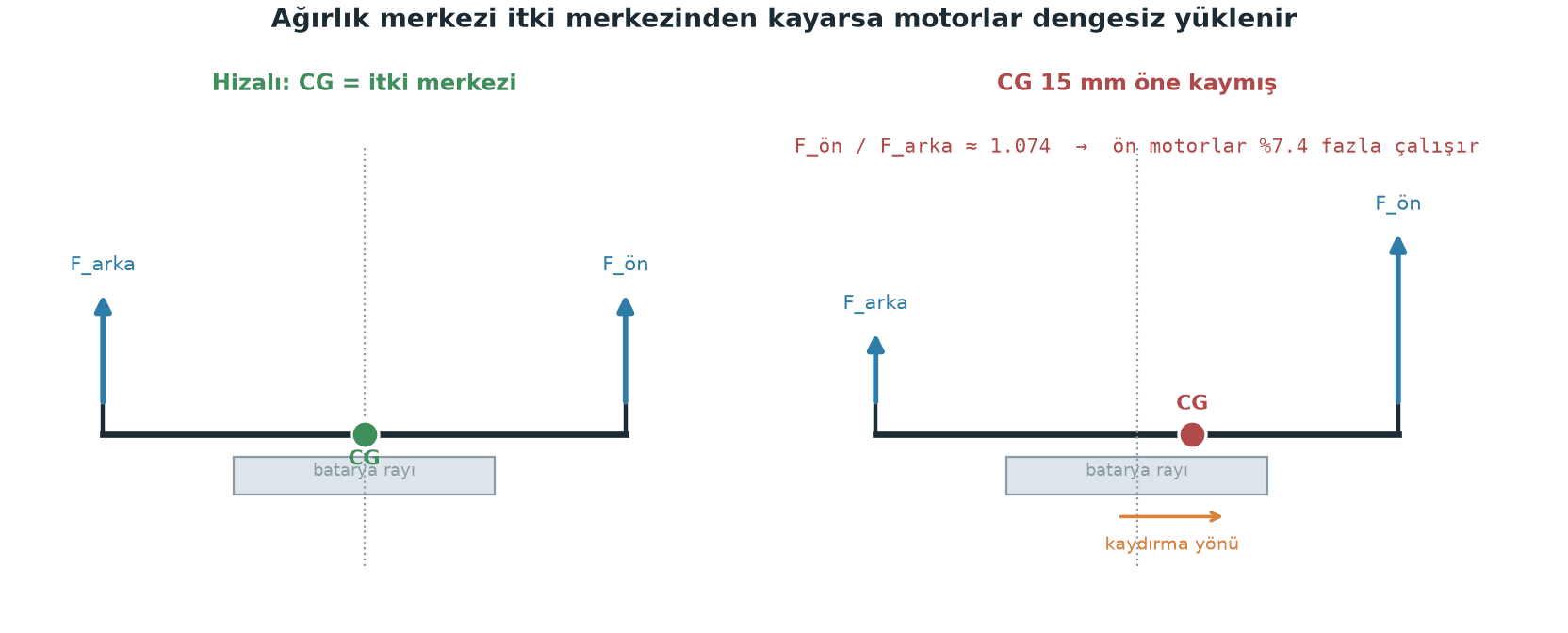
A multirotor tries to rotate about its center of thrust, the geometric mean of the motor axes. If the CG sits off that point, the aircraft has to hold a permanent moment balance just to stay level — meaning some motors work harder all the time.
The simple two-dimensional balance (front/rear motor pair, longitudinal spacing L, total weight W, CG offset d):
F_front+F_rear=W
F_front· (L/2) −F_rear· (L/2) =W·d→
F_front=W/2 +W·d/L→
F_rear=W/2 −W·d/LAsymmetry ratio = 2
d/L
Worked example — a 3.0 kg aircraft, the 15" quad above (L = 406 mm), battery sitting 15 mm too far forward:
Asymmetry = 2 × 15 / 406 = 0.074 → 7.4%
F_front= 1.5 kg × (1 + 0.074) ≈ 1.61 kg-f (per pair)F_rear= 1.5 kg × (1 − 0.074) ≈ 1.39 kg-f
The front motors are producing about 15% more thrust than the rear ones. That costs you three things: the motors doing the extra work run hotter, thrust headroom is consumed asymmetrically so one side saturates first in an aggressive maneuver, and tuning gets artificially difficult because the autopilot papers over the offset with its I term. A 15 mm shift, meanwhile, is small enough to appear just from tightening the battery strap differently.
Aircraft that release a payload have one more trap: with our servo-based airdrop mechanism, the CG changes the instant the payload leaves. That is why we put the mechanism as close to the CG as we could, ideally directly underneath it — so after a release from ~20 m the aircraft does not have to hunt for a new trim. The battery is the single heaviest item, so in practice it sets the CG; keep it on a sliding rail and do your balancing with it. Lead weight is a last resort.
Mount the flight controller near the CG horizontally as well. ArduPilot's design notes say this outright: the aircraft rotates about its center of mass, so if the autopilot sits at that point the acceleration it measures corresponds to real airframe motion; further out, centrifugal components contaminate the measurement.
Layered layout and maintenance access
Splitting the layout into layers makes both the CG and the maintenance easier. Ours looks roughly like this:
Bottom layer: Battery (on a sliding rail), power distribution board, ESCs. The heavy, frequently swapped items go lowest, and the high-current wiring stays short.
Middle layer: Flight controller (Pixhawk class), on vibration dampers, as close to the frame center as possible.
Top layer: Companion computer (Jetson Orin NX), telemetry, GPS mast — the components that make heat or carry antennas sit in the airflow.
Underside: SIYI A8 mini gimbal camera and the airdrop servo, both close to the CG's vertical axis.
Maintenance access is part of the design. There are three things you will touch over and over in the field: the battery, the SD card, and the propellers. None of them should require taking three layers apart. The rule we set for ourselves: swapping the battery takes zero screws, reaching the flight controller takes four at most.
Stiffness and resonance: the arm's quiet sabotage
A flexible arm has a natural frequency the motor can excite. As motor RPM approaches that frequency the arm goes into resonance, accelerometer noise explodes, and the autopilot's position estimate falls apart. The ArduPilot documentation is blunt about it: arm flex is the leading source of asynchronous vibration, and arms should be as rigid as you can make them.
You can get a rough estimate by modeling the arm as a cantilever beam carrying the motor mass at its tip:
Area moment of inertia (hollow round tube):
I= π · (D⁴ −d⁴) / 64Tip stiffness:
k= 3 ·E·I/L³Natural frequency:
f= (1 / 2π) · √(k/m)
Worked example — a carbon tube of 25 mm outer / 23 mm inner diameter, 250 mm free length, 200 g at the tip (motor plus mount), E = 70 GPa:
I= π · (25⁴ − 23⁴) / 64 = π · 110 784 / 64 ≈ 5437 mm⁴k= 3 · 70 000 N/mm² · 5437 mm⁴ / 250³ mm³ ≈ 73 N/mm = 73 000 N/mf= (1/2π) · √(73 000 / 0.2) ≈ 96 Hz
Now stretch that arm from 250 mm to 300 mm — only 20%. Because k ∝ 1/L³, stiffness drops to 0.58 of its old value and frequency to √0.58 = 0.76 of its old value:
f≈ 96 × 0.76 ≈ 73 Hz
The reference point is the motor's rotation frequency: f_motor = RPM / 60. On multicopters nearly all vibration comes from that frequency and its harmonics. Assume a 15" aircraft hovers around 4000 RPM and you get f_motor ≈ 67 Hz — the 96 Hz arm has comfortable margin, the 73 Hz arm has almost none. Lengthening the arm by 20% was enough to drop the frame straight into the resonance band. Aim to keep f_arm ≥ 1.5 × f_motor,max; and the cheapest way to buy stiffness is diameter, not wall thickness (I ∝ D⁴).
Confirm the result in the log. Per ArduPilot's vibration measurement documentation, VIBE X/Y/Z should stay below 30 m/s²; above 30 you can start seeing trouble, and above 60 m/s² position and altitude hold almost always break down. The clipping counters (Clip0/1/2) should ideally stay at zero; a counter that climbs steadily through a log points to a serious vibration problem.
Safety: Take the propellers off before you test arm stiffness by hand. Check the motor mounting screws before every flight — a loose motor pedestal means resonance and a thrown propeller.
Common traps
Setting the CG once and forgetting it. Gimbal angle, payload, even a different brand of battery moves the CG. On an aircraft whose payload configuration changes, a CG check belongs on the preflight list.
Long, thin arms. Stretching an arm to fit a bigger prop looks tempting, but stiffness falls off as
1/L³. If you lengthen an arm, grow its diameter too.A layout you cannot take apart. Epoxying an ESC to the arm looks clean; it stops looking clean the day you have to strip the whole arm to replace one ESC in the field.
Mounting the FC rigidly — or hanging it from an over-soft suspension. ArduPilot recommends "short-linkage damping": the board does not need more travel than the vibration amplitude. Dangling mounts are a new resonance source in their own right.
Burying the antennas under carbon. Carbon is conductive; GPS and telemetry performance drops in the frame's shadow.
Trying to fix vibration with filters alone. Software filters (harmonic notch included) are a genuine tool, but as the ArduPilot documentation stresses, aliasing noise has to be fixed at the source — that is, in the mounting and in frame stiffness.
Practical summary
Design backwards: payload → thrust → prop diameter →
R ≥ (Dp + g) / (2·sin(π/N))→ arm length. The frame is the output of that calculation, not the input.Be generous with tip clearance. Treat ArduPilot's ≈12.7 mm as the floor; work with 20–30 mm to allow for arms that flex.
Measure the CG, don't guess it. The asymmetry ratio is
2d/L; on a 400 mm frame a 15 mm offset is already a 7% thrust imbalance. Keep the battery on a sliding rail.Buy stiffness with diameter.
I ∝ D⁴andk ∝ 1/L³. Aim to keep the arm's natural frequency above1.5 × f_motor,max.Verify it in the log. Check VIBE on the first flight: below 30 m/s² is good, above 60 m/s² is a flight safety issue. If the clipping counters are climbing, go back to the mechanics before you touch the software tuning.
Get the frame right and tuning becomes easy; get it wrong and tuning turns into an effort to paper over a mechanical problem with PID gains. We wrote up our full integration experience in our SUAS 2026 journey; and if you want to try frame parameters before you fly them, our SITL + Gazebo guide is a reasonable starting point.
