
FIG. 01
RECORD DATA
Category
Mechanics
TARİH
Two complaints almost always show up together in the field. The first one: the aircraft is holding position in Loiter but its altitude is slowly creeping upward, and a "Vibration compensation ON" message pops up on the ground station. The second: in the video from that same flight, vertical lines ripple as if the image had turned to jelly.
These are not two separate faults. They are the same root cause — mechanical vibration in the airframe — showing its face in two different sensors. The IMU on the flight controller (inertial measurement unit: accelerometer + gyroscope) mistakes the vibration for real motion, and the position estimate goes bad. The camera's CMOS sensor, meanwhile, records the vibration straight into the image.
In this post we walk through how we measure vibration, how we find its frequency, and how we order the software fix (notch filter) against the mechanical ones (balancing, isolation, gimbal). The order matters: measure first, reduce it mechanically second, filter last.
Vibration claims two victims
The IMU side. ArduPilot's EKF (Extended Kalman Filter) fuses accelerometer data with the barometer and GPS to produce velocity and position estimates. High-frequency noise riding on the accelerometer skews that estimate, and the most typical result is that altitude control falls apart. ArduPilot ships a vibration failsafe that is enabled by default for exactly this case (FS_VIBE_ENABLE). If the EKF's vertical velocity and vertical position innovations are positive while the velocity variance climbs to 1 or above, and that condition holds for 1 second, altitude control switches to an algorithm that tolerates vibration better (but is less precise) without changing flight mode. You see "Vibration compensation ON" on the ground station; the aircraft leaves the state 15 seconds after the EKF returns to normal.
Let us clear up a common misconception here: the widening spiral in Loiter, the so-called "toilet bowl" effect, is attributed first and foremost to a compass problem in the ArduPilot documentation (usually magnetic interference from power cables routed under the FC). Vibration has a different signature: altitude drift, position wander, and high VIBE values in the log.
The camera side. Cameras with CMOS sensors read the frame out line by line (rolling shutter). If the sensor shakes while that readout is in progress, the top rows and the bottom rows see the scene at different instants, and straight poles start to wobble. This is the jello effect. The ArduPilot documentation ties jello directly to unbalanced propellers and motors. The high-frequency component also produces motion blur over the exposure time — and that corrupts the input to our YOLO-based detection pipeline at the source.
Sources and their telltale symptoms
Source | Typical symptom | First thing to check |
|---|---|---|
Propeller imbalance | X and Y both high | Prop balance, cracks and nicks |
Motor balance / bearing wear | X and Y both high | Turn the motor by hand, feel for play or roughness |
FC mounting (too rigid or too loose) | Only X or only Y high | Damping material and cable tension |
Propeller tracking error, bent shaft | Z axis high | Adapter concentricity, motor shaft play |
Arm/frame resonance | Sudden spike in a specific throttle band | Arm stiffness, loose screws |
This per-axis breakdown comes from ArduPilot's vibration measurement page, and it cuts troubleshooting time dramatically.
Safety. Prop balancing and motor checks are done with the propellers off the motors and the battery disconnected. Never use a cracked, nicked, or repaired propeller — imbalance is the least of its problems, since it can come apart while spinning. Connect the battery only after the props are mounted and the aircraft is secured.
Measuring: the VIBE message and its thresholds
ArduPilot logs a VIBE message on every flight. VibeX/VibeY/VibeZ are the standard deviation of the primary accelerometer's output, reported in m/s/s. The Clip0/Clip1/Clip2 counters increment every time an accelerometer hits its measurement limit (16G).
Measurement | Value | What it means |
|---|---|---|
VibeX/Y/Z | < 30 m/s/s | Normally acceptable |
VibeX/Y/Z | 30–60 m/s/s | Position/altitude problems possible |
VibeX/Y/Z | > 60 m/s/s | Almost always a problem |
Clip counters | 0 | The target |
Clip counters | < 100 (hard landing, etc.) | Acceptable |
Clip counters | Climbing steadily through the log | Serious vibration problem |
The first step is to open the log in Mission Planner and plot VIBE. Do not look at the flight as a whole; look at the hover and forward-flight segments separately, because some resonances only appear in a specific throttle band.
Finding the frequency: batch sampling and FFT
Amplitude answers "is there a problem?"; frequency answers "where is it coming from?" ArduPilot can write raw IMU samples to the log:
After a short hover flight, Mission Planner's FFT tool plots four spectra: ACC0/ACC1 (pre-/post-filter accelerometer) and GYR0/GYR1 (gyroscope). In the documentation's examples the motor-driven peak sits around ~200 Hz on a small aircraft and around ~100 Hz on a large Copter/QuadPlane; on a 5-inch quad, a pronounced peak was seen at 180 Hz in hover.
You can work out the frequency you expect ahead of time:
f_motor= RPM / 60 — Hz, the fundamental frequency of the imbalance
f_blade= (RPM xblade_count) / 60 — Hz, the blade passing frequency
Worked example — ESC telemetry reports 4800 RPM in hover with a 2-blade propeller:
f_motor= 4800 / 60 = 80 Hzf_blade= (4800 x 2) / 60 = 160 Hz
If the spectrum shows a peak at 80 Hz, the source is propeller/motor imbalance. This calculation is what lets you tell whether the peak you measured really comes from the motors or from a frame resonance.
The notch filter: cutting the noise where it lives
Blanket low-pass filters (INS_GYRO_FILTER, INS_ACCEL_FILTER) suppress every high frequency together and add latency to the control loop. A harmonic notch filter instead cuts only the motor frequency and its harmonics. Since motor RPM changes with throttle, the notch center frequency has to track it, and INS_HNTCH_MODE decides how:
Mode | Source | When to use it |
|---|---|---|
0 | Fixed frequency | Constant-RPM systems, quick experiments |
1 | Throttle-based (default) | When there is no ESC telemetry — the most common choice |
2 / 5 | External RPM sensor | If the sensor is fitted |
3 | ESC telemetry | If the ESCs report RPM, the most direct method |
4 | In-flight FFT | When nothing else is available; the documentation notes that the latency of the FFT calculation can make this perform worse than a well-set-up throttle-based notch |
For a throttle-based setup, the documentation gives these relationships:
Parameter | Value | Note |
|---|---|---|
| 1 | |
|
| The hover peak frequency read off the FFT |
|
| |
|
| The |
For better tracking across a wide throttle range, use this reference instead:
INS_HNTCH_REF=hover_thrustx (min_freq/hover_freq)^2
Worked example — hover_freq = 80 Hz, hover_thrust = 0.35, and the lowest frequency seen in the log min_freq = 60 Hz:
INS_HNTCH_FREQ= 80INS_HNTCH_BW= 80 / 2 = 40INS_HNTCH_REF= 0.35 x (60/80)^2 = 0.35 x 0.5625 = 0.197 -> ~0.20
If you are going to use FFT mode, set FFT_ENABLE = 1 (a reboot is required), INS_HNTCH_MODE = 4, and INS_HNTCH_REF = 1 (no scaling). INS_HNTCH_HMNCS lets you filter the harmonics at multiples of the fundamental as well.
A filter is not a fix, it is a cover-up. Fix the mechanics first.
The mechanical fix: balancing and isolation
The gist of ArduPilot's vibration damping page is this: propellers should be balanced with a good manual balancer, motor bearings should be free of wear, and the prop adapter should be concentric and true. As the documentation puts it, motor balance can make a big difference, especially on cheap motors. Arms should be as rigid as you can make them — aluminum or carbon fiber arms bend and twist less, so they pass along less vibration.
The goal when isolating the flight controller is to attenuate high- and mid-frequency vibration while still letting the board's real low-frequency motion through. The methods in use are foam (double-sided adhesive, in 1–2 cm squares at the four corners), gel tape, 3D-printed damper mounts, O-ring suspension, and earplug mounts.
The critical point is matching damper stiffness to the mass being isolated. The documentation warns about this explicitly: nearly every off-the-shelf solution on the market is designed for a mass at least 5–10 times heavier than an average autopilot. In other words, a badly chosen damping ball can be worse than no damper at all. Too much is as bad as too little.
Another detail that often gets overlooked: the wiring. If the cables running to the FC are stiff and pulled taut, vibration bypasses the isolation entirely. The documentation's recommendation is to use flexible wire with strain relief on every cable.
Gimbal: 2-axis or 3-axis?
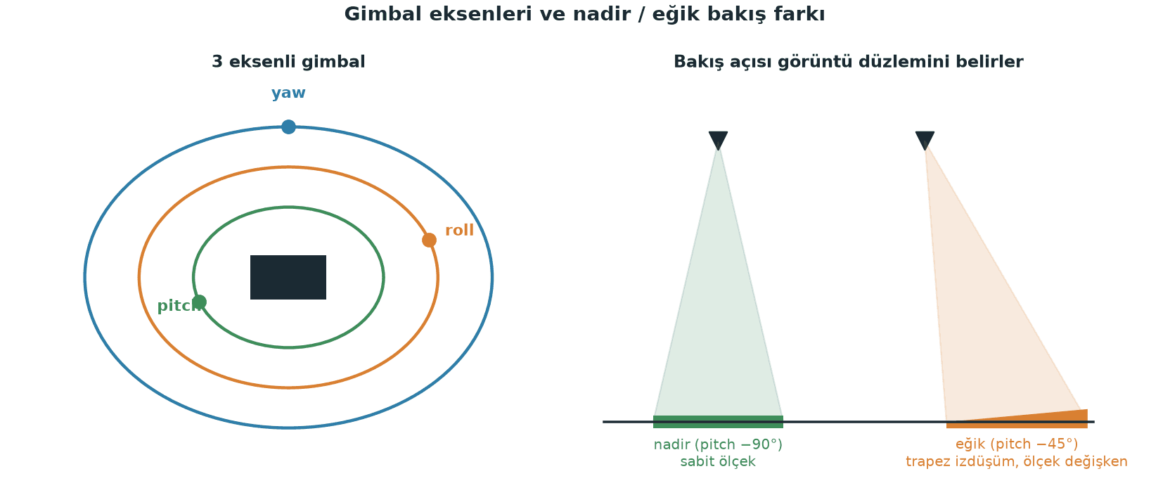
A gimbal is an active system that compensates for low-frequency changes in airframe attitude (roll, pitch). It does not solve high-frequency vibration — that is handled by the soft interface layer in the camera's own mount.
2-axis (pitch + roll) | 3-axis (pitch + roll + yaw) | |
|---|---|---|
Compensates for | Pitch and roll | Pitch, roll and yaw |
Weight / power | Lower | Higher |
When to use | Missions dominated by nadir (straight-down) views; tight weight budget | Missions that must stay locked onto a fixed target, level or oblique views |
On our SUAS 2026 aircraft we use a SIYI A8 mini (3-axis, 1080p RTSP, 81° horizontal FOV). The ArduPilot-side setup:
The nadir view (pitch = -90) matters for image processing: with the camera pointing straight down, the image plane is parallel to the ground, scale stays roughly constant across the frame, and the pixel-to-meter conversion can be done from a single altitude value. In an oblique view the same object has a different pixel size at the top of the frame than at the bottom, which complicates methods that rely on a scale assumption, such as SAHI sliced inference. Holding the angle steady gives us a consistent image stream instead of a perspective that shifts frame to frame — we send gimbal commands from the companion computer over MAVLink to hold that angle for the whole mission.
Common pitfalls
Bolting the FC straight to the frame. A rigid mount pipes all of the airframe's high-frequency energy into the accelerometer. The opposite is a mistake too: an over-soft mount starts the board oscillating at its own low frequency, and the EKF reads that as aircraft motion.
Damping balls with the wrong stiffness. A damper that is too stiff for the autopilot's mass damps nothing; one that is too soft goes into resonance. Account for the full mass the damper is isolating (the FC plus everything attached to it).
Running the wiring taut. Vibration travels through the cable instead of through the damper. Leave slack in every cable.
Flying a damaged propeller because "it will do." A nicked or repaired prop is both unbalanced and a safety risk.
Papering over a mechanical problem with the notch filter. If the clip counter is climbing, the accelerometer is already saturating, and no filter can rescue a saturated sensor.
Hard-mounting the camera to the gimbal. The gimbal solves the low frequencies; jello is solved by a soft rubber, silicone, or foam layer underneath the camera.
Looking for vibration in a ground test. The vibration signature shows up in hover and during throttle changes; spinning the motors on the bench will not give you valid data.
Practical summary
Measure first. After every flight, look at the
VIBEplot and the clip counters. Target: under 30 m/s/s on all three axes, clip counters flat.Then find the frequency. Fly a hover with
INS_LOG_BAT_MASK=1andINS_LOG_BAT_OPT=4, read the peak frequency off Mission Planner's FFT, and compare it with what you expect fromRPM/60.Fix the mechanics. Prop balance, motor bearings, adapter concentricity, arm stiffness, screw torque. Skip this step and everything that follows is palliative.
Size the isolation to the mass. Match damper stiffness to the FC's mass, leave the cables slack, and treat the gimbal mount as a separate problem from the frame.
Filter last. Set the harmonic notch to the hover frequency you measured (
FREQ = hover_freq,BW = hover_freq/2,REF = hover_thrust) and verify the change with a fresh log.
Not breaking that order turned out to be one of the biggest time-savers in our SUAS 2026 preparation. Vibration is one of the few shared variables that hits flight control and image processing at the same time; once you start measuring it properly, you win on both sides at once.
