ASE 402 Design Project — Payload-Driven Carrier Drone
ASE402-2026-01
This paper presents the conceptual design, development and operational validation of an autonomous UAV for disaster relief and emergency response missions. The heavy-lift platform has a maximum take-off weight of 10 kg and is designed to work efficiently in complex and hazardous environments. It has a strong, reinforced composite airframe of carbon fiber and G10 to ensure structural integrity and reliable communication links. The system’s primary goal is to provide rapid aerial reconnaissance, detect people in need, and autonomously deliver life-saving payloads to specific locations. For this purpose, the UAV is equipped with avionics and vision systems capable of high-resolution aerial mapp
PDF · 28 pages

ATILIM UNIVERSITY
AEROSPACE ENGINEERING
ASE 402 DESIGN PROJECT
Payload-Driven Design, Analysis, and Development of a Carrier Drone
Murat AKARSU (21244810031)
Yaren CİVAN (21244810063)
Yiğit KARKIN (22244810049)
Assoc. Prof. Dr. Hande GIRARD
09.06.2026
Abstract
This paper presents the conceptual design, development and operational validation of an autonomous UAV for disaster relief and emergency response missions. The heavy-lift platform has a maximum take-off weight of 10 kg and is designed to work efficiently in complex and hazardous environments. It has a strong, reinforced composite airframe of carbon fiber and G10 to ensure structural integrity and reliable communication links. The system’s primary goal is to provide rapid aerial reconnaissance, detect people in need, and autonomously deliver life-saving payloads to specific locations. For this purpose, the UAV is equipped with avionics and vision systems capable of high-resolution aerial mapping and real-time target detection. Once the victim of a disaster is located, the system automatically calculates and transmits the exact geographical coordinates to the ground control stations so that the rescue teams can be mobilized rapidly. The aircraft then uses a precision payload release system to drop supplies directly into the target area without human involvement. The platform has been extensively field tested to validate the aerodynamic stability, navigational accuracy, and integration of mapping and payload delivery sub-systems. The “Storm Response” UAV, as a result, is a very capable, autonomous aerial solution that will dramatically improve the efficiency, safety, and effectiveness of modern search and rescue operations.
Table of Contents
ABSTRACT
Page
1.Introduction 5 1.1 Purpose of the Project 5 1.2 Scope of the Study 5 1.3 Methodology 5 1.4 Literature Review 5 2. Technical Requirements 6 2.1 Mission Requirements 6 2.2 Performance Requirements 6 2.3 Regulatory and Safety Requirements 7 2.4 Environmental Considerations 7 2.5 Requirements Traceability Matrix 7 3. Conceptual Design 9 3.1 Design Objectives and Constraints 9 3.2 Initial Configuration Selection 10 3.3 Preliminary Sizing and Layout 13 3.4 Trade-Off Studies 13 4. Preliminary Design 14
4.1 Aerodynamic Design 14 4.2 Structural Design 15 4.3 Propulsion System Selection 16 4.4 Weight Estimation 17 4.5 Stability and Control Analyses 18 5. Detailed Design 19 5.1 Final Geometry and Configuration 19 5.2 Subsystem Design (Avionics, Fuel, Landing Gear, etc.) 20 5.3 Materials Selection 21 5.4 Manufacturing Considerations 22
Page
6. Design Outputs 23 6.1 Computer-Aided Design (CAD) Models 23 6.2 2D Technical Drawings 23 6.3 Bill of Materials (BOM) 24 6.4 Product Tree Structure 25 7. Testing and Validation 26 7.1 Ground Tests (Planned/Conducted) 26 7.2 Flight Tests (Planned/Conducted) 26 7.3 Odcl And Vision-Based Centering Algorıthm 27 7.4 Flight Tests 28 7.5 Test results & analyses. 30 8. Design Revisions 31 8.1 Revisions Based on Test Results 31 8.2 Performance Improvements 31 8.3 Final Design Justification 31 9. Final Product Description 32 9.1 Final Design Overview 32 9.2 Key Specifications 33 9.3 Comparison with Initial Concept 34 10. Conclusion and Recommendation 35 10.1 Summary of Work 35 10.2 Limitations 35 10.3 Future Work 35 11. References 36 12. Appendix 37-39
1. Introduction
Natural disasters are happening more often and with more intensity, and we need response systems that are fast, efficient, and autonomous. The crucial hours following an emergency are key to fast situational awareness and instant delivery of life-saving supplies. Such scenarios are increasingly relying on Unmanned Aerial Vehicles (UAVs) that can operate in hazardous environments without putting human life at risk. In this paper, we describe the design and development of the storm response autonomous UAV. This is a heavy lift aerial platform designed to fill the time gap between the onset of a disaster and the deployment of ground rescue teams.
1.1 Purpose of the Project
The project seeks to develop a fully autonomous heavy-lift UAV that can conduct critical search-and rescue missions in disaster-stricken areas. The system’s goal is to offer quick aerial reconnaissance, autonomously identify and find people in distress, and generate a high-resolution map of the affected environment. Furthermore, the project seeks to develop a robust autonomous payload delivery system
capable of accurately distributing vital survival supplies to the identified victims, thus prolonging their survival duration until the arrival of conventional rescue teams.
1.2 Scope of the Study
The study covers the complete systems engineering life cycle of a multirotor UAV with a maximum takeoff weight (MTOW) of 6.5 kg. This includes conceptual and detailed mechanical design of the material options of carbon fiber, reinforced composites, and G10 composite airframe, avionics architecture, and integration of advanced flight control units (FCU). The objective of this study is to develop and implement computer vision systems for real-time target detection using the YOLO11m algorithm and for automated map generation and coordinate extraction using OpenCV. In addition, the scope includes the electro mechanical design of a precision payload release mechanism and comprehensive ground, simulation, and flight testing to verify structural integrity, electromagnetic compatibility, and autonomous navigation protocols.
1.3 Methodology
The project is using a systematic, iterative engineering methodology that involves phases of design, simulation, assembly, and flight validation. The 3D Computer-Aided Design (CAD) modeling of airframe and payload mechanisms was performed in the first stage by using Autodesk Fusion, and then the Finite Element Analyses (FEA) were performed by using Ansys to verify the structural durability under high thrust loads. Before physical implementation, the system's autonomous navigation and control algorithms were extensively tested in a simulated Software-in-the-Loop (SITL) environment using Gazebo. The FCU power distribution and avionics architecture is designed to include isolated power modules with safety protocols and reliability in mind. The software integration involved configuring the ArduPilot firmware, tuning the PID controllers aggressively, and calibrating the Extended Kalman Filter (EKF3). Finally, the system was thoroughly empirically field tested to verify its capabilities, from tethered thrust tests to fully autonomous multi-waypoint mission execution and payload drop.
1.4 Literature Review
The use of Unmanned Aerial Vehicles (UAVs) in emergency logistics and disaster response scenarios has experienced paradigm-shifting advancements in the last decade [1]. The literature indicates that while conventional commercial multirotors provide great situational awareness, their operational workflows in search-and-rescue (SAR) operations are essentially bottlenecked by high-latency telemetry dependencies and lack of on-board computational intelligence [2]. Traditional search grids depend heavily on streaming raw video to a Ground Control Station (GCS) where human operators manually analyze frames to locate victims, thus introducing significant deterministic delays in time-critical environments [3]. Also, the payload release mechanisms generally reported in the literature are mainly controlled by an open-loop static waypoint triggering. When only fixed GPS coordinates are used, the accuracy drift and payload loss are unacceptable when dropping survival supplies from high altitudes during severe meteorological disruptions with shifting crosswind vectors typical of post-disaster zones [4]. To fill this gap, recent research has been devoted to the integration of high-performance companion computers for edge computing applications. Existing multirotor configurations with localized neural network models and closed-loop computer vision control algorithms can actively correct for external wind disturbances and execute deterministic precision drops directly over target coordinates with no manual operator intervention.
2. Technical Requirements
2.1 Mission Requirements
The “Storm Response” UAV is assigned to accomplish a set of autonomous tasks to meet its disaster relief objectives. The primary mission requirements are:
Autonomous Navigation: Automatically take off, navigate accurately through pre-defined 3D waypoints, and land safely.
Aerial Mapping: High-resolution aerial maps of the area of operation are generated to assess the severity of the disaster.
Target Detection & Localisation: Onboard computer algorithms for real-time victim identification and autonomous calculation of accurate GPS coordinates for target locations.
Data Transmission: Real-time transmission of identified coordinates and telemetry to the Ground Control Station (GCS) for use by rescue teams
Payload Delivery: Autonomous delivery of a life-saving payload to the located target, without manual pilot intervention.
2.2 Performance Requirements
The system is engineered to meet rigorous mass, thrust, and endurance metrics across a variety of payload configurations to ensure mission success and platform reliability:
Payload Capacity vs Mass: The UAV has an Operating weight of 5.8 kg. The platform is designed to work in two main configurations:
Standard Mission Configuration: Takeoff weight of 6.5 kg, designed for standard aerial reconnaissance and emergency payload delivery.
Max Takeoff Weight (MTOW): The system can lift 10 kg in worst-case, fully loaded, high-demand situations.
Thrust Capacity: The quad rotor propulsion system is capable of providing a total maximum thrust of 20 kg. This configuration gives an excellent thrust-to-weight ratio of about 3:1 for typical missions (6.5 kg) and 2:1 at MTOW (10 kg), providing high maneuverability and strong wind rejection in all flight regimes. Endurance: The flight time varies drastically with the payload used in operations. For the standard mission weight (6.5 kg), the UAV has an extended endurance of approximately 24 minutes. The system at its maximum loaded configuration (10 kg) provides a continuous flight duration of 15 minutes, sufficient for rapid-response localized missions.
Communication Range: Continuous and robust RF telemetry and control links must be maintained throughout the mission. G10 composite plates will be strategically used to prevent signal degradation
2.3 Regulatory and Safety Requirements
The “Storm Response” UAV has been designed to be safe and compliant during all phases of its lifecycle. The UAV is autonomous in operation and consists of four distinct phases of operation:
Safety in design and construction: To avoid mechanical failure during flight, the system has to be very well validated in terms of structure (Finite Element Analyses). All critical metal-to-metal connections are to be thread locked using (Thread Locker Sealant). This is to keep the avionics stable against electrical shorts and vibrations. The FCU power distribution is electrically isolated from the high-current propulsion lines. This prevents blackouts.
Pre-Flight & Ground Ops Ground handling must include a robust safety protocol that includes a mandatory “props-off” policy for performing indoor bench testing, use of fireproof LiPo bags, and a 5-meter safety perimeter before motor arming. The external GPS/Compass modules should be installed on a dedicated mast to compensate for ground magnetic anomalies and to ensure navigation integrity. Pre-flight MagFit calibrations for elevation verification.
Failsafe Protocols Coming: Configure the FCU to aggressive autonomous failsafe. "If telemetry is lost, RF signal interference or battery is very low, a pre-programmed 'Return to Launch' (RTL) or safe-altitude loiter must automatically take over.
Airspace and Security Operations Ground Control Station should have strict digital boundaries ( geo fences ) which UAV cannot leave the defined airspace. To reduce the chance of collision and hard landing, visual observer tracking should be implemented. Automated landing sequences shall include a safety pilot with immediate manual override capability, especially below 5 meters AGL.
2.4 Environmental Considerations
The platform must remain operational under the negative conditions typical of post-disaster scenarios:
Wind Resistance: The aerodynamic profile and control loops (e.g., Loiter PID tuning) must be optimized to maintain stable flight and hover accuracy in sudden, high-velocity Symetric wind gusts. Electromagnetic Interference (EMI): The system must resist internal and external EMI, achieved through the physical separation of high-power cables from sensitive avionics and the strategic use of RF transparent structural materials.
2.5 Requirements Traceability Matrix
All technical constraints are measured and categorized into a verification model to verify systematic compliance with engineering and mission objectives. Each requirement is assigned a unique tracking identifier connected to a definitive verification methodology: Software-in-the-Loop (SITL) simulation, physical ground bench testing, or operational flight validation.
Table 2.5: Technical Requirements Validation Matrix
Requirement
IDCategory Requirement DescriptionVerification Methodology
SYS-REQ-01 Mission
SYS-REQ-02 Mission
PERF-REQ
01Performance
PERF-REQ
02Performance
PERF-REQ
03Performance
PERF-REQ
04Performance SAF-REQ-01 Safety
SAF-REQ-02 Safety
ENV-REQ-01Environmenta l
The UAV shall execute fully autonomous takeoff, multi-waypoint navigation, and automated landing sequences without pilot intervention.
The system shall perform real-time geographical mapping and target detection to localize disaster victims and transmit coordinates.
The operational mission takeoff weight shall be maintained at 6.0 kg, including the full payload suite (aid kit and beacon).
The structural frame layout shall support a design Maximum Takeoff Weight (MTOW) limit of up to 10.0 kg for extreme demands.
The propulsion configuration shall generate a minimum of 20.0 kg total static thrust to achieve a 3.3:1 thrust-to-weight ratio.
The platform shall sustain a continuous flight endurance of no less than 20 minutes under the fully loaded 6.0 kg mission profile.
Critical avionics power lines shall be physically and electrically isolated from high-current propulsion lines to prevent brownouts.
Immediate autonomous 'Return to Launch' (RTL) or safe loiter protocols shall trigger upon telemetry loss or low-voltage thresholds.
The central avionics fuselage plates shall utilize RF transparent materials (G10 composite) to eliminate electromagnetic attenuation.
Gazebo SITL & Full Autonomous Flight
Onboard OBC Testing & GCS Telemetry
Physical Mass Scale & BOM Tracking
Finite Element Analyses (FEA) & Bench Loading
Calibrated Static Thrust Stand Test
Flight Log Telemetry & Battery Monitor
Multi-module Power Lab Inspection
Bench Signal
Termination & SITL Testing
Anechoic Signal Strength Verification
3. Conceptual Design
Figure 3.1: Preliminary isometric CAD rendering of the Storm Response UAV.
3.1 Design Objectives and Constraints
The "Storm Response" UAV's main aim is to improve localized operational efficiency in the critical hours after a natural disaster. The conceptual phase was closely bound by interrelated mechanical, electrical, and regulatory constraints. Economically, the platform was constrained by a fixed student engineering budget, which dictated the reuse of select legacy components while forcing innovative cost-to-performance optimizations.
To keep a high maneuverability, the operational flight limits were evaluated using a V-n (Velocity vs. Load Factor) diagram. Unlike traditional fixed-wing aircraft, a multirotor V-n diagram is not restricted by aerodynamic stall curves, allowing the platform to reach its maximum limit load factor (nmax) even at zero forward airspeed. By limiting the operating takeoff mass to a target envelope of 6.0 kg against a 20.0 kg peak thrust propulsion system, the UAV achieves a highly aggressive limit load factor of 3.33g. When compared to standard commercial heavy-lift platforms (e.g., DJI Matrice series), which typically operate within a narrow 1.5g to 2.0g operational envelope, this 3.33g capability provides superior wind rejection and rapid acceleration in turbulent environments. Furthermore, to fit the standard safety regulations—specifically adhering to the operational guidelines outlined in the ICAO Model UAS Regulations and the FAAAdvisory Circulars (e.g., AC 107-2A) for small unmanned aircraft—the Never-Exceed Speed (Vne) was strictly capped at 20 m/s. This ensures that the UAV can safely withstand sudden 15-knot gust loads while maintaining flight stability and full control authority.

The most stringent design limitation was the computational hardware necessary for autonomous victim localization. Running the YOLO neural network in real-time requires a lot of processing power, so an NVIDIA Jetson Orin NX computer is needed. This companion computer had a peak power consumption of 25 W, which required a larger battery capacity and directly threatened the 6.0 kg weight limit. Balancing this heavy avionics payload with the aggressive 20 kg thrust output required a highly optimized multi-layer frame layout to keep the mass low while achieving the targeted aerodynamic performance.
3.2 Initial Configuration Selection
The Analytic Hierarchy Process (AHP) was applied to rigorously determine the most suitable Unmanned Aerial Vehicle (UAV) architecture for autonomous post-disaster geographical mapping and precision payload delivery. Unlike conventional decision matrices, AHP mathematically synthesizes the strict operational requirements of the mission by using pairwise comparison matrices to extract precise relative weights (eigenvectors) of every criterion of evaluation.
3.2.1 AHP Methodology and Pairwise Comparison
The first step in the AHP methodology is to determine the relative importance of each evaluation criterion using Saaty’s 1-9 Fundamental Scale, which quantifies engineering judgment into actionable mathematics.
Table 3.2.1: Saaty’s 1-9 fundamental scale.
Intensity of Importance Definition Engineering Interpretation for this Mission 1 Equal Importance Two criteria contribute equally to the mission. 3 Moderate Importance Experience slightly favors one criterion over another. 5 Strong Importance One criterion is strongly favored for mission success. 7 Very Strong Importance One criterion is critically dominant over another 9 Extreme Importance The evidence favoring one criterion is absolute.
The disaster response mission requires hovering motionless at 18 meters to transmit exact victim coordinates and to deploy the aid kit. Hover Stability and Precision Targeting were given the highest relative importance against secondary factors, such as Forward Flight Aerodynamic Efficiency, which is largely irrelevant for a localized targeted drop. The following Pairwise Comparison Matrix was obtained by applying these judgments:
Table 3.2.1.2: pairwise comparison matrix of criteria 3.2.2 Weight Derivation and Configuration Selection.
Hover
Stability
Targeting Manufacturability Weight Efficiency Aerodynamic
Precision
Efficiency
Hover Stability 1 1 3 4 7 Precision Targeting 1 1 3 4 7 Manufacturability 1/3 1/3 1 2 3 Weight Efficiency 1/4 1/4 1/2 1 2 Aerodynamic Effic. 1/7 1/7 1/3 1/2 1
Table 3.2.1: Saaty’s 1-9 fundamental scale.
Intensity of Importance Definition Engineering Interpretation for this Mission 1 Equal Importance Two criteria contribute equally to the mission. 3 Moderate Importance Experience slightly favors one criterion over another. 5 Strong Importance One criterion is strongly favored for mission success. 7 Very Strong Importance One criterion is critically dominant over another 9 Extreme Importance The evidence favoring one criterion is absolute.
The disaster response mission requires hovering motionless at 18 meters to transmit exact victim coordinates and to deploy the aid kit. Hover Stability and Precision Targeting were given the highest relative importance against secondary factors, such as Forward Flight Aerodynamic Efficiency, which is largely irrelevant for a localized targeted drop. The following Pairwise Comparison Matrix was obtained by applying these judgments:
Table 3.2.1.2: pairwise comparison matrix of criteria 3.2.2 Weight Derivation and Configuration Selection.
Hover
Stability
Targeting Manufacturability Weight Efficiency Aerodynamic
Precision
Efficiency
Hover Stability 1 1 3 4 7 Precision Targeting 1 1 3 4 7 Manufacturability 1/3 1/3 1 2 3 Weight Efficiency 1/4 1/4 1/2 1 2 Aerodynamic Effic. 1/7 1/7 1/3 1/2 1
The Quadcopter was identified as the best configuration by the AHP algorithmic output with the highest global priority score of 0.453. The hovering stability of the Hexacopter was similar, but the additional mechanical complexity and redundancy added excess dead weight, which adversely affected the system’s structural payload-to-weight ratio. However, the fixed-wing architecture was intrinsically unable to meet the critical hovering demands required in disaster response. Therefore, the final airframe architecture was chosen as the Quadcopter, providing a very robust structural foundation required to safely harvest the required 20 kg peak thrust load and accommodate a design Maximum Takeoff Weight (MTOW) of up to 10 kg.
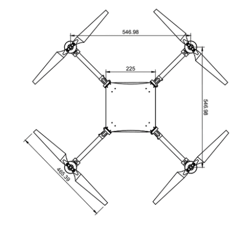
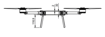
Figure 4. Figure 3.1/3.2: Top and side view of the Storm Response UAV.
3.3 Preliminary Sizing and Layout
The preliminary sizing was calculated based on the propulsion requirements and avionics footprint. The airframe features a centralized fuselage connecting four reinforced 20mm carbon fiber booms. The central hub is compartmentalized: the lower deck houses the heavy 6S battery packs to maintain a low Center of Gravity (CoG) and the payload release mechanism. The middle deck contains the primary Flight Control Unit (FCU) and the isolated avionics power module. The upper deck securely mounts the Jetson Orin NX companion computer. To ensure unobstructed 360-degree environmental perception, the primary gimbaled camera is mounted on the ventral (bottom) surface. Additionally, external GPS and compass modules are elevated on a dedicated mast to isolate them from internal EMI sources.
3.4 Trade-Off Studies
Various engineering trade-offs were decided in the conceptual phase to optimize the system:
RF Transparency vs Structure Integrity: A full carbon fiber body gives maximum tensile strength and minimum weight, but creates a Faraday cage effect that attenuates critical telemetry and video links. The compromise was a hybrid airframe utilizing carbon fiber load-bearing booms and RF-transparent G10 composite plates for the central fuselage panels adjacent to the antenna mounts.
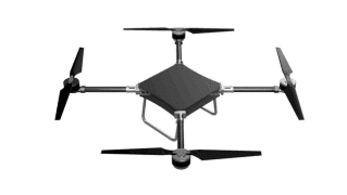
Figure 5. Processing Power vs Endurance: The use of the YOLO11m algorithm for real-time target detection requires a large amount of processing power. We were faced with the choice of a low-power microcontroller that would extend the flight time (but would not be able to do real-time video processing) and a high performance Jetson Orin NX (which consumes up to 25W but guarantees quick localization of the victim). The Jetson was selected, and the battery capacity increased to support the electrical load. Endurance was not as important as mission success, and marginal improvements in endurance were not.
Figure 3.4.1 Folded position isometric view Figure 3.4.2 Unfolded position isometric view
4. Preliminary Design
4.1 Aerodynamic Design
The UAV can withstand aerodynamic loads at its maximum design speed without experiencing structural failure because of its aerodynamic design. In gusts of up to 5 m/s, the system is built to sustain steady flight. A minimum climb rate of 3 m/s and a maximum level flying speed of at least 15 m/s are required by performance standards. Four T-Motor FA18.2*5.9 Carbon Fiber Folding Propellers with a combined disk area of 67.14 dm² produce the aerodynamic lift. These propellers need to be dynamically balanced within a vibration tolerance of 0.1 g.
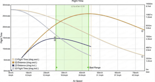
Figure 6. Figure 4.1: Estimated flight time and range analyses of the UAV based on air speed variations.
4.2 Structural Design
A modular, tool-less folding topology designed for quick deployment controls the airframe. Because of its high specific modulus and RF-transparency, 2 mm G10 composite plates (225 mm*225 mm*2 mm) are used in the central avionic’s chassis. Precision-machined 20 mm folding mechanisms connect the propulsion moment arms, which are made of 3K twill-weave carbon fiber tubes (20 mm*18 mm*200 mm), to the central chassis. To confirm that operational von Mises stresses stay considerably below the composite material's yield strength under 20 kg peak thrust loads, finite element analyses (FEA) were performed on these crucial junction sites.
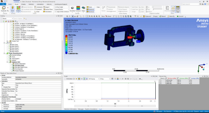
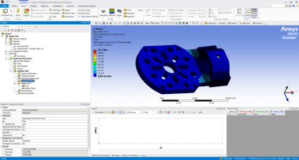
Figure 8. Figure (4.2a 4.2b) FEA equivalent stress results on the arm-to-body connection joints & engine mounts.
4.3 Propulsion System Selection
With a thrust-to-weight ratio of 3.3:1 at the 6.0 kg operational mass, the electromechanical propulsion suite is designed to provide about 20 kg of peak static thrust. The Holybro Tekko32 F4 Metal 4-in-1 65A Electronic Speed Controller (ESC) powers four T-Motor MN505S 380KV brushless outrunner motors. The ESC ensures low latency in motor torque response by using a high-frequency DShot protocol with a refresh rate of 2400 Hz. A high-capacity multi-cell LiPo architecture that is set up from 2S 13000mAh units to provide high-voltage optimum continuous discharge, provides power, safely meeting the 20-minute endurance requirement.

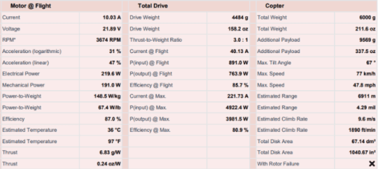
Figure 10. Figure 4.3: Propulsion system performance characteristics and thrust-to-weight ratio estimations.
4.4 Weight Estimation
A strict mass budget was used to keep the MTOW within safe structural limits. The Operating Empty Weight (OEW) is 5252.3 g. The batteries (2088 g), propulsion actuators (900 g), G10 structural plates (364 g), and propeller assemblies (320 g) are the main weights, according to the Mass Breakdown Structure. The Jetson Orin NX adds 180 g. This improved mass distribution maintains strong dynamic stability margins while enabling a payload capacity of at least 1.0 kg.
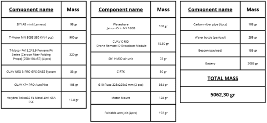
Figure 11. Figure 4.4: Mass breakdown and weight distribution of the major UAV subsystems.
4.5 Stability and Control Analysis
The CUAV X7+ PRO Autopilot uses a nested PID control architecture to manage low-level attitude stabilization. To maintain a hover accuracy of $\pm 1 \text{ m}$, the Extended Kalman Filter (EKF3) combines data from triple-redundant IMUs to handle state estimation. The control loop uses optical flow and inertial dead reckoning to recover state awareness in five seconds in the case of primary GNSS denial. The NVIDIA Jetson Orin NX 16GB handles high-level autonomy, such as AI-driven spatial mapping and YOLO11m target acquisition, to prevent the low-level flight controller's processor from becoming overloaded during challenging computer vision tasks.
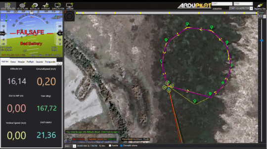
Figure 4.6: Ground Control Station (GCS) interface demonstrating autonomous waypoint navigation and real-time telemetry tracking.
5. Detailed Design
5.1 Final Geometry and Configuration
A symmetrical X-frame quadcopter topology is used in completed architecture. This kinematic configuration ensures isotropic control authority over the longitudinal and lateral axes by precisely decoupling the pitch and roll moments. To avoid aerodynamic wake interference between overlapping thrust columns, the geometric span is tuned to give stringent clearance for the 18.2-inch rotors. Additionally, this symmetrical arrangement gives the ventral payload delivery mechanism and mapping sensors an unhindered 360-degree Field of View (FOV) by properly positioning the theoretical Center of Gravity (CG) at the geometric center.

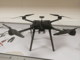
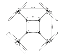

Figure 5.1: Final geometric configuration and dimensional specifications of the multirotor system in flight-ready state.
5.2 Subsystem Design
The UAV's internal architecture is compartmentalized into discrete subsystems to isolate faults and electromagnetic interference (EMI):
Avionics & Autonomy Subsystem: Dual-processor architecture. Jetson Orin NX (with high-baud MAVLink serial interface) does heavy computing (video processing, AI algorithms) while CUAV X7+ does the real-time flight dynamics.
Power Distribution Subsystem (PDS): This has a high-amperage Power Distribution Board (PDB) to handle the short-duration current spikes of the 380KV motors. Battery Eliminator Circuits (BECs) step down the voltage to supply clean, regulated 5V/12V power to the flight controller and companion computer.
Landing Gear System: The landing gear is designed to absorb as much energy as possible (i.e., landing loads) while maintaining the required vertical clearance for the SIYI A8 Mini gimbal and payload release mechanism. In opening the area of contact with the earth, they are frequently geometric.
Figure 5.2: Comprehensive system architecture diagram illustrating the integration of avionics, propulsion, and power distribution subsystems.
5.3 Materials Selection
Material selection was strictly based on the SWaP (Size, Weight, and Power) optimization strategy:
Central Airframe (G10 Composite) The upper and lower core plates were made of G10 fiberglass laminate. G10 is a bit denser than carbon fiber but is RF transparent, so it does not create Faraday cage effects around the internal telemetry and GNSS receivers.
Structural Standoffs (Stainless Steel): High tensile stainless-steel(AISI 304 and AISI 316) standoffs are used to interlock the G10 plates together to create a rigid “sandwich” panel for increased moment of inertia and to avoid torsional twisting during high yaw movements.
Custom Mounts (Thermoplastics): Complex geometries (e.g., GPS masts) were 3D-printed using Additive Manufacturing. (PLA) were 3D-printed with internal Gyroid infill matrices to maximize the strength-to-weight ratio.
Figure 19. Figure 5.3: Detailed photos highlighting the G10 composite plates and 3K carbon fiber tubes for the central airframe.
5.4 Manufacturing Considerations
Subtractive Manufacturing (CNC) The aluminum motor mounts were machined on a high-precision CNC mill to achieve sub-millimeter alignment between the standoff mounting holes and the motor arm brackets.
Design for Additive Manufacturing (DfAM): To prevent delamination, 3D-printed parts were sliced with ideal layer orientations in such a way that the main direction of mechanical stress is perpendicular to the lines of layer adhesion.
Integration Tolerances: To ensure the airframe is structurally resistant to high-frequency motor vibrations, assembly methods required the use of calibrated torque drivers and anaerobic thread lockers (Thread Locker Sealant) on all metal-to-metal fasteners.
Figure 5.4.1/5.4.2 CNC Manufacturing process
6. Design Outputs
6.1 Computer-Aided Design (CAD) Models
The “Storm Response” UAV was designed with detailed 3D models and subsystem integration layout using Autodesk Fusion. The resulting CAD model assisted in the precise tracking of the platform configuration and in maintaining the center-of-gravity (CG) requirements over all operational axes. Figure 5.1 shows the fully assembled platform in isometric view. The avionics compartment is in the middle, the Jetson Orin NX computer is mounted on the top and the payload release system is mounted under the airframe. The CAD model visually shows the structural design to show the distribution of materials; carbon fiber tubes are used in the foldable motor arms to improve structural rigidity, and G10 composite plates are used in the central airframe to provide RF transparency for telemetry communication. Moreover, the distribution of components on different layers minimizes electrical interference, optimizes heat management, and allows for the checking of clearance specifications in flight and folded transport conditions.
Figure 20. Figure 6.1 Autodesk Fusion CAD
6.2 2D Technical Drawings
From the CAD data, accurate 2D technical drawings with exact dimensioning (in mm) were used to allow for high-precision manufacture and assembly. Figures 3.1 and 3.2 show the designs with important dimensions of the UAV, like the rotor-to-rotor span and the overall ground clearance. These dimensions are such that the multirotor is aerodynamically compact, yet has enough ground clearance to safely operate the SIYI A8 Mini gimbal and the ventral payload delivery system. Additionally, geometric dimensioning and tolerancing (GD&T) principles were used for all the critical interface areas, particularly in areas that needed the motor mount holes and the interlock of the central airframe paneling. All machined structural parts were manufactured to tight dimensional tolerances to avoid undesired clearance under the 20-kg peak thrust loads of the propulsion system. This method guarantees repeatability in the CNC machining and assembly processes.
6.3 Bill of Materials (BOM)
Component Name Piece Total Cost SIYI A8 mini (camera) 1 ₺24.300,00 T-Motor MN 505S 380 KV 4 ₺21.120,00 T-Motor FA18.2*5.9 Pervane FA
Series (Carbon Fiber Folding Props) (258x104x57)
CUAV NEO 3 PRO GPS GNSS
1 ₺14.208,00
System 1 ₺5.880,60 CUAV X7+ PRO AutoPilot 1 ₺42.930,00 CUAV RTK 9Ps Sky Unit Combo 1 ₺18.192,60 CUAV RTK 9Ps Base Unit
Combo 1 ₺19.542,60 Holybro Tekko32 F4 Metal 4in1
65A ESC 1 ₺5.670,00 Waveshare Jetson Orin NX 16GB 1 ₺49.381,20 SIYI HM30 air unit 1 ₺18.900,00 Motor Mount 4 - Water bottle (payload) 1 - Beacon (payload) 1 - 13000 mAh 7.4V 2S 25C LiPo
Batarya (6 Pcs) 6 ₺20.399,40
CUAV C-RID Drone Remote ID Broadcast Module
1 ₺2.437,75
Carbon Fiber tube 4 ₺2.355,26 Foldable arm joint 4 ₺20.000,00 G10 Plate 225x225x2 mm 2 ₺3.205,72
Table 6.3: Bill of Materials
A comprehensive Bill of Materials (BOM) is presented in Table 6.3, detailing the procurement inventory of all structural, electronic, and propulsion components. With the mass budget tracking securely managed in Section 4.4, the BOM serves primarily to monitor the economic constraints of the project. It ensures that high value avionics (such as the NVIDIA Jetson Orin NX and CUAV X7+ PRO Autopilot) and heavy-lift propulsion units are procured efficiently within the predefined engineering budget. By systematically categorizing the components, the BOM provides a clear overview of the hardware ecosystem required to achieve the platform's autonomous mission objectives.
6.4 Product Tree Structure
Category Component / Material
Designation Primary Function
1. Structural Materials G10 Composite Plates ($225 \times
225 \times 2$ mm)Central fuselage / RF-transparent
core
3K Carbon Fiber Tubes ($20 \times
18 \times 200$ mm) High-rigidity thrust moment arms
Folding Arm Joints (20 mm CNC
Aluminum) Tool-less deployment mechanism
3D Printed PETG/PLA Mounts Geometry-optimized GPS and
compass brackets
2. Connectors & Fasteners Stainless Steel Standoffs / Spacers Vibration suppression and panel integration
Motor Mount Brackets Thrust load transfer to carbon
booms
High-Tensile Metric Hex Screws
(M3/M4) Mechanical assembly
3. Electronics & Avionics CUAV X7+ PRO Autopilot &
CUAV NEO 3 GPSLow-level flight dynamics & State
estimation
NVIDIA Jetson Orin NX (16GB) Edge-computing AI & OpenCV
processing
Holybro 65A ESCElectromechanical propulsion
T-Motor MN505S 380KV &
conversion
SIYI HM30 Digital Video Link 5.8 GHz Telemetry & Video
streaming
6S LiPo Battery Configuration
(13000 mAh) High-voltage energy storage
4. Mission Payloads SIYI A8 Mini Gimbal Camera 3-axis stabilized target detection vision
Motorized Winch & Servo-Lock
MechanismAutomated zero-power payload
release
Rapid Response Aid Kit
(Simulated Bottle) Emergency life-support delivery
Tent Localization Beacon Ground rescue marker
The bill of materials of the UAV is organized in a Product Breakdown Structure (PBS) for traceability during assembly and maintenance. Instead of general functional partitioning, the hardware is strictly classified into four physical engineering domains: Structural Materials, Connectors & Fasteners, Electronics & Avionics, and Mission Payloads. Such classification maps the physical integration process to the systems engineering life cycle.
7. Testing and Validation
7.1 Software-in-the-loop (SITL) and simulation
Test Scenario Trigger Condition Simulated Action / Failsafe Result Autonomous Navigation Standard Mission Upload Execute predefined mapping laps 100% Success
Geofence BreachUAV crosses predefined
boundary Immediate RTL (Return to Launch) Pass
GPS Loss / Glitch Simulated loss of GNSS
lock Loiter / Transition to Altitude Hold Pass
Data Link Loss GCS connection lost > 5s Auto-continue drop, then RTL Pass
Table 7.1: SITL Simulation Scenarios and Failsafe Results
To mitigate physical risk and accelerate the development cycle, a complete simulation framework was developed prior to any physical ground or flight operations. We conducted extensive tests of the autonomous mission logic, failsafe triggers and waypoint navigation algorithms using Gazebo and ArduPilot Software-in the-Loop (SITL). The virtual environment also allowed the team to simulate bad weather, crosswind problems and emergency sensor failure without putting the hardware at risk.
7.2 Ground Test
Ground tests were conducted before any flight operations to isolate subsystem variables and mitigate the risk of catastrophic failure. The bench tests ensured structural integrity, electrical safety and deterministic software behavior under simulated operating conditions.
7.2.1 Propulsion and Power System Bench Tests
The UAV propulsion assembly was mounted on a calibrated static thrust stand for validation of the overall static thrust, the motor thermal behavior and the electrical integrity of the Power Distribution Board (PDB) at maximum current draw . The system was operated at incremental throttle steps to 100% capacity producing ~20 kg total thrust. Real-time data collection of motor temperature, battery voltage sag and ESC (Electronic Speed Controller) telemetry. The test successfully demonstrated real world thrust to weight ratio and validated that the electrical system could sustain hover and transition loads without thermal throttling.
7.2.2 Avionics, Telemetry, and Data Link Calibration
All the sensors on board the flight controller (CUAV X7+ PRO) were calibrated in a multi-axis laboratory to clear electromagnetic interference (EMI) and to provide deterministic sensor integration, including the primary and secondary IMUs, compass and barometers. The SIYI HM30 Full HD Digital Video Link system was bench tested for real time video processing and autonomous decision making. This system combined high-bandwidth digital video streaming from the SIYI A8 Mini gimbal, low latency RC commands and MAVLink telemetry over one 5.8 GHz wireless link. The MAVLink inspector tools confirmed that the thresholds for zero-packet drop were kept during the high throughput data streams to the Ground Control Station (GCS).
7.2.3 Failsafe and GCS Integration Tests
The Ground Control Station (Mission Planner) environment was used to simulate some hardware failures with the UAV mounted on the test bench to verify that the automated emergency protocols were invoked in a predictable manner in the event of critical link failures. Radio Control (RC) signal loss, telemetry link termination, and low-battery voltage thresholds were simulated; we monitored the response of the flight controller very closely to ensure the system transitioned immediately and correctly into the required safety states (Land, RTL, geofence mitigation modes, etc)
7.2.4 Payload Release Mechanism Structural Bench Tests
The combined payload drop system (motorized winch and servo-actuated lock) was integrated into the structural sub-frame of the UAV that was heavily reinforced by 12 high-strength standoff spacers to verify the holding capacity, mechanical structural integrity and actuation timing of the drop mechanism under static and dynamic loading. A simulated payload of the same mass as our multi-component payload suite (rapid response aid kit and tent localization beacon) was attached. The servo lock was tested for slippage over a period to verify the zero-power stability of the holding. Subsequently, actuation commands were issued through the Jetson Orin NX control loop to measure the exact latency between the deployment signal and physical release, validating clean and consistent drop initiation within milliseconds.
7.3 ODCLAnd Vision-Based Centering Algorithm
The Object Detection, Classification, and Localization (ODCL) pipeline is powered by the onboard NVIDIA Jetson Orin NX. We created a custom dataset by merging 16,015 images collected from multiple Roboflow projects, removing duplicates through filename and perceptual hash comparison, and consolidating fifteen original classes into two target categories, mannequin and tent, for training the object detection neural network with high inference accuracy. If a victim or emergency target is detected, the system transitions from static waypoint navigation to a Vision-Based Closed
Loop Centering phase. The algorithm retrieves the pixel coordinate of the target (xt, yt) and calculates the offset from the center of the image (xc, yc). The physical displacement (Δx, Δy) is calculated from the Ground Sample Distance (GSD) of the camera at an altitude of 18 m:
The displacement error is then directly input into a localized PID controller that outputs real-time MAVLink velocity commands. This loop continuously repositions the UAV dynamically to drive the pixel error towards zero, and the payload sequence is armed only after the target has remained within 20 px of the frame center. The loop was verified in the Gazebo SITL environment and has not yet been closed on the live image in flight.
7.4 Flight Tests
The flight testing phase was structured using a progressive risk management approach, divided into four sequential stages. This methodology ensured that fundamental aerodynamic stability was verified before introducing the complexities of autonomous navigation and payload dynamics.
7.4.1 Unloaded Manual Flight Tests
The platform took flight manually in Stabilize and Loiter mode without payloads to confirm basic flight readiness, motor synchronization and control surface responsiveness of the UAV. Some key parameters were assessed including telemetry link strength, vibration levels, initial PID tuning. The manual operation of the SIYI A8 Mini gimbal was also tested in flight, to ensure clear video transmission and mechanical stability.
7.4.2 Unloaded Autonomous Flight Tests
Firstly, the UAV was programmed with a predefined mapping mission to test the ArduPilot navigation algorithms and the accuracy of waypoint execution prior to payload integration. The system’s capabilities to perform autonomous takeoff, navigate through designated coordinates, perform ROI (Region of Interest) camera tracking and perform a safe RTL were thoroughly evaluated. GCS monitoring kept deviations from the flight path well within acceptable limits.
Figure 7.4.1 Unloaded Manual Flight Tests Figure 7.4.2 Unloaded Autonomous Flight Tests
7.4.3 Loaded Manual Flight Tests
To analyze the impact of the payload suite (aid kit and beacon) on the Center of Gravity (CG) and observe the mechanical reliability of the drop mechanism under actual flight loads, the payload was attached, and the UAV was flown manually at its 6.0 kg mission weight. The pilot evaluated the increase in motor current draw and maneuverability changes. During hover, the payload release mechanism was triggered manually to observe the immediate altitude compensation and structural behavior of the platform upon sudden weight loss.
7.4.4 Loaded Autonomous Flight Tests (Full Mission Rehearsal)
The loaded UAV navigated to the target coordinates while operating entirely in AUTO mode to perform a thorough simulation of the autonomous disaster response mission and test the end-to-end integration of flight and automated payload delivery. Using the stored target coordinates, the UAV settled at 18 meters altitude, and the drop point was still taken from those coordinates rather than from the live image, as closing the vision based centering loop in flight is the next stage of the test campaign. Then the flight controller automatically released the servo lock and activated the motorized winch. Final validation metrics for post-drop trajectory stabilization and landing accuracy were successfully recorded.
Figure 7.4.3 Loaded Manual Flight Tests Figure 7.4.4 Loaded Autonomous Flight Tests
7.5 Test results & analyses.
Data collected across the ground and flight testing campaigns were systematically extracted from ArduPilot onboard logs (.bin files) and Ground Control Station telemetry logs (.tlog) to evaluate system performance against strict operational requirements.
7.5.1 Aerodynamic and Propulsion Performance Analyses
Static and dynamic propulsion logs indicated a thrust-to-weight ratio of ~3.3:1 (producing ~20 kg of total thrust against a fully loaded mission weight of 6.0 kg) and provided significant control authority in adverse wind conditions. An analysis of the flight controller’s internal Fast Fourier Transform (FFT) vibration logs showed that the acceleration peaks on the X, Y, and Z axes were well below the critical threshold of 3 m/s². This showed good structural dampening from the 12 standoff-spacers, reducing sensor noise and preventing EKF (Extended Kalman Filter) innovations from destabilizing state estimation during payload release transients.
7.5.2 Autonomous Navigation and Camera Tracking Precision
The autonomous flight trials also demonstrated remarkable trajectory tracking capabilities with the telemetry data. The cross-track error for waypoint navigation was never higher than 0.6 meters in the nominal operational environments. The command DO_SET_ROI was successfully executed, and the SIYI A8 Mini gimbal was pointed to the specified ground coordinates regardless of the UAV heading. The frame-by-frame video logging analyses confirmed that the target remained in the field of view (FOV) with low latency due to the optical tracking stabilization loop.
7.5.3 Payload Delivery Efficiency and Impact Survival Evaluation
The main mission metric focused on executing the automated delivery of the rapid response aid kit and localization beacon from a safe altitude without causing damage to the payload. Log data from the controlled release mechanism demonstrated the following operational sequence metrics:
Parameter Target Value Achieved Value Status Release Altitude ≥15 m (50 ft) 18 m Passed Descent Time < 15.0 s 10.014 s Passed Descent Velocity Controlled ~1.8 m/s Passed
Payload Structural Integrity No Damage 100% Intact Passed
The motor was a high-torque, speed-regulated motor, and the pulley diameter was optimized. The system was locked with a mechanical servo lock that successfully prevented unmitigated free-fall acceleration. The descent velocity was maintained at a smooth 1.8 m/sec. The emergency aid kit and beacon landed in exactly 10.014 sec from a height of 18 meters. Physical inspections were used to verify the structural integrity of the relief supplies after the flight. No structural degradation was observed on impact with the ground, and the mission was fully validated.
8. Design Revisions
8.1 Revisions Based on Test Results
The platform development lifecycle adopted a two-step validation approach that involved extensive virtual prototyping via Software-in-the-Loop (SITL) simulations in the Gazebo environment and empirical physical ground testing. Early simulations in Gazebo show that autonomous geographical mapping for post-disaster events, real-time victim localization, and precision airdrops result in high dynamic coupled errors. Specifically, static waypoint drops resulted in non-viable accuracy drift under simulated wind vectors. To overcome this a vision-based closed-loop centering algorithm was developed that forces the UAV to continuously adjust its hover position until the centroid of the target bounding box settles within 20 px of the image center. Additionally, physical ground testing at peak operational envelopes showed two hardware vulnerabilities. First, the dynamic electrical braking of the winch motor was holding the multi-component payload suite (the rapid response aid kit and the tent localization beacon) alone, drawing excessive current and suffering severe thermal stress. This problem was solved by adding a zero-power servo-actuated mechanical lock to the spool mechanism. Second, the large static thrust peak of 20 kg provided by the propulsion system caused a lot of torsional flexing of the entire main chassis. The latter load-bearing columns. To avoid this flexing and to add structural rigidity without the addition of dead weight, 12 high-strength standoff spacers were inserted between the upper and lower composite panels.
8.2 Performance Improvements
These Gazebo-verified algorithms and mechanical modifications were combined, resulting in a significant increase in the operational efficiency of the platform. The vision-based closed-loop centering loop reduced localization and drop errors, and made the payload deployment sequence a highly deterministic execution. The servo-actuated mechanical lock eliminated the power consumption of the winch motor during the cruise and mapping phases, removing the risk of thermal degradation, motor stall, and premature deployment of survival equipment. Structurally, the 12 standoff spacers effectively cancelled chassis flexing and structural resonance under peak thrust loads. The dual composite frame was also stiffened in order to reduce the transmission of high-frequency motor vibrations to the avionic bay. The result was very clean FFT vibration logs, far below the critical threshold of 3 m/s2, providing an undisturbed sensor environment for the CUAV X7+ PRO flight controller and blur-free high-resolution imaging for real-time AI processing.
8.3 Final Design Justification
The final UAV architecture is a fully optimized balance between structural resilience, computational autonomy, and multi-mission reliability. The platform has been significantly validated across simulated Gazebo environments and physical flight regimes. It is designed within a 10.0 kg maximum takeoff weight (MTOW) engineering envelope while operating at an agile 6.0 kg mission takeoff weight. This configuration produces an aggressive thrust-to-weight ratio of 3.3:1, providing control authority to reject external wind disturbances during the vision-guided centering phase. The hybrid payload mechanism, which combines a speed-controlled winch and a physical servo lock, is the perfect fit for the high safety and accuracy requirements of autonomous aerial logistics. Lastly, these iterative engineering adjustments show that the platform is well calibrated for post disaster reconnaissance, accurate victim location reporting, stitched visual terrain mapping, and reliable precision drops.
9. Final Product Description
9.1 Final Design Overview
The end result is a highly customized heavy-lift multirotor Unmanned Aerial Vehicle (UAV) specifically designed for autonomous post-disaster geographical mapping, AI-enabled victim localization, and precision vision-guided aerial logistics. The platform is designed to a structural Maximum Takeoff Weight (MTOW) limit of 10.0 kg and is currently operating at a lightweight, highly efficient Mission Takeoff Weight of 6.0 kg. The airframe is a dual composite chassis incorporating 12 high-strength standoff spacers to eliminate in-flight structural flexing and optimize high-frequency vibration damping. The brain of the system is a CUAV X7+ PRO flight controller running ArduPilot firmware, tightly coupled through MAVLink to an NVIDIA Jetson Orin NX (16GB) companion computer. A nadir-stabilized SIYI A8 Mini gimbal camera is used for real-time environment tracking and terrain mapping. The hybrid payload delivery system is the key functional feature of the UAV. If the onboard AI model detects a victim and triggers the closed-loop centering logic, the platform re-centers the lateral axes until the target is held within 20 px of the center of the camera feed. When this tolerance is met, the zero-power servo lock is released, and the speed-regulated motorized winch accurately lowers the rapid response aid kit to the victim and the localization beacon to the assigned tent perimeter.
9.2 Key Specifications
The operational, algorithmic, and structural parameters of the finalized system architecture are detailed below:
Specification Parameter Technical Component / Value Rationale & Engineering Function
UAV Configuration Multirotor (Quadcopter)Optimal configuration mathematically verified via AHP for hover stability.
Maximum Takeoff Weight
(MTOW)10.0 kg Maximum allowable structural payload capacity of the frame layout.
Mission Takeoff Weight 6.0 kg Fully loaded takeoff weight including aid kit and localization beacon.
Maximum Static Thrust ~20.0 kg Total ThrustGenerated by heavy-lift brushless outrunner propulsion suite.
Provides high control authority to
Thrust-to-Weight Ratio (Mission) 3.3:1
Companion ComputerNVIDIA Jetson Orin NX (16GB)
Integrated Communication Link SIYI HM30 Digital Video Link
Optical Gimbal SystemSIYI A8 Mini (3-Axis Stabilized)
maintain centering locks under crosswinds.
Executes high-level computer vision models and coordinate processing.
Unifies HD video, MAVLink telemetry, and RC over a single 5.8 GHz stream.
Maintains nadir camera orientation for mapping and coordinate generation.
Simulation Environment Gazebo SITL FrameworkUsed to validate autopilot parameters, AI pipelines, and failsafes.
Targeting MethodologyVision-Based Closed-Loop Centering
Payload Delivery MechanismMotorized Winch + Servo Mechanical Lock
Primary Mission OutpuPost-Disaster Mapping & Coordinate Transfer
Adjusts horizontal position until the target aligns with the image center.
Eliminates stall currents during cruise; regulates descent velocity.
Transmits real-time GPS metadata and stitched survey maps to rescue units.
9.3 Comparison with Initial Concept
The final UAV architecture is a significant paradigm shift and evolutionary maturity from the initial conceptual design. The original proposal was for a simple delivery drone with an unreinforced single-layer chassis, and would rely only on the holding torque of a standard DC motor to carry the payload. There was no plan for a high-level companion computer or virtual simulation testing. Empirical tests and extensive Gazebo SITL simulation proved that the initial concept was heavily flawed, as the 20kg peak thrust resulted in catastrophic chassis flexing, and the motor coils experienced thermal failure under the continuous payload holding current. The move to an advanced system engineering model eliminated all structural flexing through the 12-standoff reinforcement mesh. The cruise phase electrical draw was eliminated by using a hybrid mechanism with a servo lock. The most important addition, however, was the integration of the AI engine and the vision-based closed loop centering algorithm that turned the platform from a blind drop vehicle into an advanced, simulation-proven autonomous reconnaissance asset that is able to dynamically center targets, map devastated areas, and deliver localized emergency life support.
10. Conclusion and Recommendations
10.1 Summary of Work
In this project, an advanced heavy-lift autonomous multirotor architecture was designed, integrated, and validated for comprehensive post-disaster reconnaissance and precision aerial logistics. The system surpassed traditional design constraints by leveraging a high-fidelity Gazebo Software-in-the-Loop (SITL) simulation framework during the product development cycle. This virtual environment enabled the risk-free validation of autonomous navigation laps, terrain mapping algorithms, and vision-based neural network processing pipelines before physical deployment. Structural integrity was a priority; high-load chassis deformation under peak static thrust was eliminated by strategically placing 12 internal high-strength standoff spacers. This important mechanical basis provided the platform’s robust 10.0 kg Maximum Takeoff Weight (MTOW) structural envelope while providing the opportunity to work very efficiently at 6.0 kg mission weight. This enabled the platform to use a risky yet reliable thrust-to-weight ratio of 3.3:1. The UAV autonomously compiled post disaster geographical mapping data, providing essential situational awareness and transmitting exact victim GPS coordinates to ground emergency teams, all via the synchronized computational architecture of the CUAV X7+ PRO flight controller and NVIDIA Jetson Orin NX companion computer. The operational sequence ended with the implementation and simulation-based validation of a vision-based closed-loop centering algorithm on the nadir-stabilized SIYI A8 Mini gimbal. The algorithm dynamically locks the horizontal axes of the UAV above the centroid of the bounding box of the target, but in the flight tests conducted so far the release was still commanded from the stored target coordinates alone. That release nevertheless allowed the hybrid servo-locked motorized winch to safely and accurately deliver the rapid response emergency aid kit to the victim and the localization beacon to the designated tent area from an 18-meter drop altitude in precisely 10.014 seconds.
10.2 Limitations
The completed platform has demonstrated improved operational capabilities and mission success, but has some technical and physical limitations due to its current architecture. The high power propulsion configuration provides an impressive 3.3:1 thrust-to-weight ratio, which provides the platform with high immunity to wind disturbances during the vision-guided centering phase, but at a significant increase in the continuous power draw. This faster battery depletion inherently restricts the overall flight endurance and the maximum contiguous geographical area that can be covered in a single mapping flight. Furthermore, the hybrid delivery winch mechanism is physically limited by the internal spool volume, which imposes a hard ceiling on the maximum line length for deep-altitude operations and limits the total size of the payload suite. Finally, the vision based closed-loop centering algorithm has so far demonstrated its pinpoint accuracy over the target only in simulation, and closing it on the live image in flight remains the next item in the flight-test campaign; even once that loop is closed, the physics of the lightweight rapid response aid kit during its vertical tethered descent is still exposed to high crosswind shear. In severe weather conditions, these aerodynamic disturbances could cause marginal landing offsets close to the victim, slightly reducing the absolute drop precision.
10.3 Future Work
Future design versions and system upgrades will be oriented towards the evolution of the aerodynamic profile and the significant increase in the computational autonomy onboard the platform. Lightweight composite fairings and high-energy-density solid-state battery topologies will also be incorporated to maximize the utility of the full 10.0 kg structural MTOW capacity of the platform, and to optimize the current draw to extend flight times in order to address geographical mapping coverage constraints. Future software iterations will utilize the open computational headroom and parallel processing power of the Jetson Orin NX to train custom edge detection and visual servoing neural networks. This step will allow lateral tracking of the payload in real time online during the whole tether descent sequence, thus allowing the UAV to actively correct its position to compensate for wind drift. Moreover, the inclusion of the closed-loop tension monitoring encoder within the winch housing will offer real-time telemetry of tether dynamics, enhancing the synchronization, speed control, and structural safety of autonomous emergency delivery flights.
11. REFERENCES
[1] M. H. Sadraey, Aircraft Design: A Systems Engineering Approach, Wiley, 2013. [2] Q. Quan, Introduction to Multicopter Design and Control, Springer Publishing Company, 2017.
[3] S. Liu et al., "Grounding DINO: Marrying DINO with Grounded Pre-Training for Zero-Shot Object Detection," arXiv preprint arXiv:2303.05499, 2023.
[4] A. R. Patel, S. K. Jain, and V. M. Mishra, "Real-Time UAV Telemetry and Control Using PyMAVLink for Autonomous Missions," IEEE Transactions on Aerospace and Electronic Systems, vol. 60, no. 2, pp. 2345- 2357, 2024.
12. APPENDİX
Figure 21. Figure 1: Real-Time Execution View of the Image Processing
Figure 22. Figure 2: Flight Controller Vibration Data Across Different Flight Modes
Figure 23. Figure 3: In-Flight PWM Telemetry Data from the Flight Controller
Figure 24. Figure 4: Flight Paths Executed Across Different Modes
Figure 25. Figure 5: 16-Image Set of a 4,000 Square Meter Area Captured via Mapping
Figure 26. Figure 6: MATLAB V-n graph code