Technical Design Report
AUAV-TDR-2026-02
This article presents the design, development and testing strategy of our autonomous UAV designed for the SUAS 2026 competition. The UAV is geared towards disaster relief and emergency response missions. The UAV is equipped with avionics and vision systems capable of high-resolution aerial mapping and real-time target detection. The heavy-payload platform has a maximum takeoff weight of 10 kg and is designed to operate efficiently in complex and hazardous environments. It features a robust, reinforced composite fuselage made of carbon fiber and G10 to ensure structural integrity and reliable communication links. When a disaster victim is located, the system automatically calculates precise g
PDF · 11 pages
Atılım UAV Team Technical Design Report 2026
Abstract
This article presents the design, development and testing strategy of our autonomous UAV designed for the SUAS 2026 competition. The UAV is geared towards disaster relief and emergency response missions. The UAV is equipped with avionics and vision systems capable of high-resolution aerial mapping and real-time target detection. The heavy-payload platform has a maximum takeoff weight of 10 kg and is designed to operate efficiently in complex and hazardous environments. It features a robust, reinforced composite fuselage made of carbon fiber and G10 to ensure structural integrity and reliable communication links. When a disaster victim is located, the system automatically calculates precise geographic coordinates and transmits them to ground control stations, allowing rescue teams to be quickly mobilized. The aircraft then uses a precision payload drop system to drop materials directly onto the target area without human intervention. The platform has undergone extensive field testing to verify aerodynamic stability, navigation accuracy, and the integration of mapping and payload carrying subsystems.
ACKNOWLEDGMENT
We would like to express our sincere gratitude to our academic advisor, Dr. Halis Demirbaş, for his invaluable technical and logistical advice and continuous support. We also extend our thanks to all our professors, former and current team members, and mentors who pioneered the transition to autonomous systems and paved the way for our current work. We also owe a debt of gratitude to our sponsors. We are grateful to ASELSAN, one of the most important defense industry companies in our country, for the financial support they provided to enable us to build our UAV in the best possible way. Furthermore, the Ministry of Youth and Sports provided us with a facility where we can carry out production and conduct not only mechanical work but also team meetings and social activities. We thank them very much for their assistance. WupSoft and FSM Demirbaş helped us in procuring the basic parts of our UAV. Our sponsors who provided financial
and team member product support are: Pegem Akademi, Çatkaya, ÖzcanSu, BallıKuyumcu Offroad, and Gezerler Construction. We thank them all very much for their support and offer our respects.
I. COMPETITION STRATEGY
A. Strategic Vision
Our strategic vision is to develop a highly reliable autonomous aerial platform capable of supporting disaster relief and emergency response operations while accomplishing all SUAS mission objectives with maximum precision and operational efficiency. Rather than optimizing individual mission tasks independently, our design philosophy focuses on integrating navigation, aerial observation, target localization, and payload delivery into a single coordinated autonomous system. The platform is designed to rapidly survey disaster-affected areas, generate accurate situational awareness, and assist rescue teams by providing precise target localization and autonomous delivery of emergency supplies. Achieving this objective requires not only accurate autonomous navigation but also seamless interaction between the mechanical, electrical, avionics, and imaging subsystems throughout the entire mission. Reliability was established as the primary design driver from the earliest stages of development. The aircraft incorporates a modular mechanical architecture, an RTK-assisted navigation system, stabilized aerial imaging, and a robust communication infrastructure to ensure dependable operation under demanding environmental conditions. Special attention was given to structural integrity, electromagnetic compatibility, thermal management, and maintainability to reduce operational risks and enable rapid field servicing when required.
Our engineering strategy emphasizes system-level integration rather than isolated subsystem optimization. Every design decision from component placement and power distribution to payload deployment and communication architecture was evaluated according to its contribution to overall mission success, reliability, and ease of operation. These holistic systems engineering approach enables the UAV to perform
autonomous navigation, high-resolution aerial observation, accurate target localization and
controlled payload delivery as a unified and dependable mission platform. Ultimately, our objective is not only to satisfy the competition requirements but also to demonstrate a practical autonomous UAV architecture that can be adapted for real-world disaster response scenarios where accuracy, reliability and rapid deployment are of critical importance.
B. Task Integration Strategy
To maximize mission efficiency and ensure reliable autonomous operation, each mission is designed not only as a standalone function but also as an integrated part of the overall UAV architecture. Navigation, target observation, communication, and payload delivery are designed to work collaboratively throughout the mission, enabling information sharing between the onboard avionics systems and the Ground Control Station (GCS). This integrated approach enables accurate autonomous waypoint navigation, continuous aerial observation, real-time mission monitoring, and precise payload deployment under varying operational conditions. Autonomous navigation is performed using the CUAV Neo3 Pro GNSS receiver and flight control unit integrated with the RTK module. The RTK-supported navigation architecture provides the centimeter-level positioning accuracy required for waypoint tracking and payload delivery. Navigation data is continuously processed by the flight control unit, allowing the aircraft to maintain stable autonomous flight while coordinating with the remaining onboard subsystems. Aerial observation and target tracking are performed using the SIYI A8 Mini camera equipped with a stabilized gimbal. Independent gimbal stabilization compensates for aircraft movement, ensuring continuous and stable image acquisition throughout the mission. High-resolution video is transmitted simultaneously to the Ground Control Station via the SIYI HM30 digital transmission system, providing real-time visual feedback for mission monitoring, target verification, and payload delivery, while also supporting onboard image processing.
Communication between the UAV and the Ground Control Station is provided via the SIYI HM30 digital transmission system using the MAVLink protocol. The communication architecture provides continuous telemetry transmission, mission updates, flight control commands and live video streaming during flight. This allows operators to monitor mission execution in real time while maintaining reliable communication between all critical subsystems. The payload delivery system is designed to support independent placement on both dummy and tent targets. Each payload is secured with a dedicated servo-driven locking mechanism and lowered via a separate 800 RPM DC motor, ensuring a controlled landing rather than free fall. The dual-channel HW-231 H-bridge motor drive independently controls both delivery mechanisms, ensuring accurate and repeatable load distribution across different mission phases while maintaining operational safety and delivery accuracy.
Continuous interaction between navigation, display, communication and payload subsystems allows missions to be executed as a coordinated autonomous workflow rather than isolated operations. This system-level integration enhances mission reliability, reduces operational complexity and ensures consistent performance throughout the entire SUAS mission.
II. DESIGN STRATEGY
Our design strategy was shaped by the operational requirements of disaster relief missions and the technical objectives of the SUAS competition. Instead of addressing each subsystem independently, the aircraft was developed as an integrated autonomous platform where mechanical, electrical, avionics, communications, imaging and payload systems were designed to work collaboratively throughout the mission. Each key mission requirement was translated into specific engineering objectives and addressed through an iterative design process emphasizing reliability, ease of maintenance and system integration. The design process focused on striking a balance between payload capacity, flight duration, navigation accuracy and structural integrity while maintaining compliance with competition constraints. Multiple design alternatives were evaluated throughout the development process, and subsystem configurations were selected based on their contribution to overall mission performance rather than isolated component optimization.
Specific engineering studies were conducted for the propulsion, mechanical structure, avionics,
communications, navigation, imaging, and payload subsystems. Throughout the development cycle, particular attention was paid to subsystem compatibility, electromagnetic compatibility (EMC), thermal management, weight distribution and ease of maintenance. These systems engineering approach enabled all subsystems to work together to form a reliable autonomous UAV capable of mapping, target positioning, autonomous navigation and precise payload delivery under challenging operational conditions.
A. Propulsion system
Our state-of-the-art propulsion system utilizes T-motors U7 Lite V2.0 490KV waterproof, Dust resistant, and extremely durable motors compatible for a UAV of this scale, providing more than enough thrust to effectively maneuver our drone at high speeds. The RTF 80A 4-in-1 8S Lite AT FPV Drone Brushless ESC was chosen to satisfy the propulsion system's high current requirements and offer dependable motor control. Six Leopard Power 13,000 mAh 25C 2S LiPo batteries coupled in a 6S2P arrangement make up the power system. This arrangement stays within the maximum permitted takeoff weight while providing the necessary operating voltage and energy capacity. Furthermore, the battery pack is designed to operate within safe discharge limits, guaranteeing sufficient flight time to accomplish each mission objective.
B. Airframe
The airframe structure is designed to provide a stiff primary load path while maintaining low mass and high field serviceability. The primary structures consist of carbon fiber tubes and composite plates, which are connected by aluminum parts that form the motor mount and the foldable joints. The main purpose of the composite plate is to keep the internal components and the bottom side is designed for the battery pack and the payload. The landing gear is connected to the bottom side of the main plate.
Secondary structures like 3 d printed brackets and mounts are used for integration and protection. Thrust loads transfer from motor mounts into carbon fiber tubes to Foldable joints to main plates, while landing loads are carried through landing gear mounts to the lower plate. To ensure stable and balanced flight, we carefully manage the center of gravity (CG) relative to the four rotors. The battery, as the heaviest component, is centrally placed on the main plate directly beneath the thrust vector of the rotors. This positioning keeps the CG aligned with the force generated during thrust, supporting a well-balanced and predictable flight. In addition, other internal components—such as the avionics, payload mechanism and structural elements are arranged to keep the CG close to the aircraft’s central axis. This intentional layout minimizes the need for large corrections and helps maintain smooth, stable flight. Our design focuses on three key modular features to maximize field serviceability and quick turnaround. First, the carbon fiber arms attach via foldable joints. These joints allow the arms to fold for transport and lock securely for flight. They connect to the main plate and can be replaced individually if damaged, without removing other structural elements. Second, the landing gear is fully plug-and-play. It can be detached or reattached without bolts or tools, making replacement quick after rough landings. Third, the battery pack is secured using hook and-loop fasteners rather than permanent fixtures. This ensures fast swapping while holding the pack firmly in place. These three modular elements ensure that critical subsystems can be serviced or replaced efficiently, minimizing downtime.
C. Airdrop
Our airdrop system uses a winch mechanism driven by DC motors and enables independent payload deployment to the mannequin and tent targets. Each payload is secured by a dedicated spool lock actuated by a servo motor; while the lock is engaged, the payload remains fixed at the bottom of the UAV regardless of motor state. Once the UAV locks onto its target and positions itself directly above the designated drop location, the release sequence begins: the servo first opens the spool lock, and only then does the dedicated 800 RPM DC motor start, lowering the payload at a controlled, constant descent speed that eliminates free-fall. When the drop is completed, the motor stops. The entire release sequence is executed at an altitude of approximately 20 m. Both motors are driven by a single HW-231 dual-channel H-bridge motor driver, allowing independent bidirectional control of each delivery mechanism. This configuration enables the two payloads to be deployed separately at different stages of the flight while providing reliable and precise control over the delivery process.
D. Software Design
Our software architecture was developed to support autonomous mission execution while ensuring seamless integration between navigation, onboard perception, mapping, and payload delivery. Rather than treating these functions as independent software modules the entire processing pipeline was designed around the operational requirements of the Search–Detect–Deliver mission, allowing multiple competition tasks to be completed during a single autonomous flight.
The software design began by translating mission requirements into measurable vision constraints. Since the SIYI A8 Mini camera has a fixed field of view, target visibility is determined primarily by flight altitude and ground sampling distance (GSD). Instead of optimizing solely for inference speed, software requirements were derived from the minimum target pixel size necessary for reliable detection under realistic flight conditions. This approach guided the selection of image resolution, detection parameters and processing architecture throughout the development process.
Ground sampling distance: With the gimbal locked at nadir, the ground footprint of a frame of width Nh pixels at altitude h above the target plane, and the resulting ground sampling distance, are
(1)
With the 81° horizontal field of view of the SIYI A8 Mini and a horizontal frame width of 1920 px, (1) gives 17.8 mm/px at the 20 m operating altitude used throughout our flight testing. A 1.7 m mannequin lying on the ground therefore spans approximately 96 px along its long axis, but its short axis spans only about 25 px, and both shrink by a factor of three once the frame is downscaled for inference. This short-axis budget is what sets the minimum usable target size and drives the choice of operating altitude.
Object detection is performed onboard using a Jetson Orin NX companion computer running a YOLO11m-based detection pipeline. Live video from the SIYI A8 Mini camera is transmitted through an RTSP stream where only the most recent frame is processed to eliminate queue latency and maintain real-time performance. Confirmed detections are geolocated and transferred directly to the autonomous guidance system allowing the aircraft to navigate toward the detected targets and initiate payload delivery without additional operator intervention.
To satisfy both detection accuracy and real-time processing requirements, several inference configurations were evaluated during development. While tiled inference significantly improved small-object detection at longer distances, its computational cost reduced processing speed below the level required for closed-loop autonomous guidance. Consequently, the operational flight configuration performs full-frame inference at 640-pixel resolution with a 0.25 confidence threshold, providing a balanced compromise between detection performance and real-time execution. Alternative TensorRT accelerated tiled inference remains available as a contingency configuration for higher-altitude mission scenarios.
Target geolocation: Because the gimbal holds the camera at nadir and absorbs aircraft roll and pitch, the target pixel (u, v) in a W × H frame defines a ray that is already expressed in a locally level forward-right-down frame; it is brought into the local NED frame by the aircraft heading ψ alone, as reported by the flight controller,
(2)
and intersected with the ground plane using the AGL altitude h, which yields the north and east offsets of the target and hence its coordinates, with latitude and longitude expressed in radians and RE the local Earth radius:
(3)
Equations (1) and (2) are two projections of the same pinhole model: the per-pixel scale 2·tan(HFOV/2)/W in (2) is the inverse focal length 1/f, with f = (W/2)/tan(HFOV/2) = 1124 px, and the ground sampling distance in (1) is that same factor projected onto the ground, GSD = h/f. Detection sizing and target geolocation therefore rest on one camera model rather than two independent calibrations.
Terminal guidance: A logged coordinate alone is not sufficient for release accuracy: it carries the geolocation error of a single detection, and the aircraft must be centered over the target at the instant of release. After navigating to the stored coordinate and settling, the aircraft therefore closes the loop on the live image rather than on the GPS fix, using image-based visual servoing. The controller drives the image-plane offset of the detected target from the frame center, e = (eu, ev) = (u − W/2, v − H/2), to zero. The offset is smoothed by an exponential moving average with α = 0.15 to reject detection jitter, and is mapped onto the body axes of the nadir camera, in which image “up” is forward and image “right” is starboard. A discrete PID law running at 20 Hz (Δt = 0.05 s) then produces body-frame velocity commands, which are rotated into the NED frame by the current yaw ψ and streamed to the flight controller as MAVLink velocity setpoints:
(4)
The gains are Kp = 0.003 and Kd = 0.004 (m/s)/px with Ki = 0.0001 (m/s)/(px·s), where the derivative gain is defined per sample difference rather than per unit time, and the integral term is clamped to prevent wind-up while the target is briefly occluded. Command magnitude is saturated at 0.8 m/s so that the aircraft converges without overshooting. Detections are reported in the full 1920 × 1080 frame, so release is armed only after the target has remained within 20 px of the frame center, which by (1) corresponds to 0.36 m on the ground at the 20 m release altitude; a target lost for a sustained period aborts the approach and returns the aircraft to the waypoint mission.
Control-loop limits: The controller uses a fixed-depth approximation of the classical interaction matrix, holding the estimated range at the release altitude rather than scaling the gain with measured range, so it is tuned for the single 20 m release altitude used throughout our flight testing. The release reported in Section III-E was still commanded from the stored geolocation alone; closing this loop on the live image is the next item in our flight-test campaign, and range-scheduled gain would be required before operating it at a materially different altitude.
E. Avionics and Electrical System
The avionics and electrical architecture were designed to ensure reliable subsystem integration while maintaining electromagnetic compatibility, thermal performance and ease of maintenance. Power and signal cables were routed separately to minimize electromagnetic interference and electronic components were arranged to improve cooling and accessibility. The Orange Cube Plus flight controller coordinates the navigation, propulsion, communication and payload subsystems during autonomous flight. Positioning is provided by the CUAV Neo3 Pro GNSS receiver together with the CRTK 9Ps RTK module enabling centimeter-level navigation accuracy for waypoint tracking and payload delivery. Communication with the Ground Control Station is established through the SIYI HM30 digital transmission system using the MAVLink protocol in Mission Planner. The HM30 also provides HD video transmission from the SIYI A8 Mini stabilized camera, whose video stream is processed onboard by the Jetson Orin NX while simultaneously providing real-time visual feedback to the operator. The system also incorporates the CUAV CRID module to satisfy Remote ID requirements.
F. Data Generation and Model Selection
The object detection system was developed using a dataset specifically curated to improve small object detection under realistic aerial operating conditions. A total of 16,015 images collected from multiple Roboflow projects were merged, duplicate images were removed using filename and perceptual hash comparison, and fifteen original classes were consolidated into two target categories: mannequin and tent. Vehicle related classes were discarded while the significant class imbalance between mannequin and tent samples was reduced through oversampling of tent images. Training data were generated using overlapping 1280 × 1280 image tiles together with hard-negative background samples collected from debris and grass environments. Model validation was performed exclusively on real aerial DJI imagery to ensure that performance metrics accurately reflected the operational environment rather than web-based datasets.
YOLO11m was selected as the object detection model because the primary limitation observed during initial experiments originated from dataset diversity rather than network capacity. The model was trained using COCO-pretrained weights at an input resolution of 1280 pixels while data augmentation techniques including scaling, flipping, rotation, mosaic augmentation and mixup were reintroduced to improve robustness against variations in object scale and viewing conditions. Alternative approaches, including a P2 detection head and a dual-model ensemble were evaluated but ultimately rejected due to their increased computational cost without sufficient operational benefit for the two-class detection problem.
G. Risk Mapping
Our mapping subsystem converts the imagery collected during the autonomous waypoint tour into a single stitched map of the Search Boundary, generated on site immediately after the survey and written directly in the submission-ready image format (Fig. 1). The design prioritizes fast on-site turnaround, robustness to the small frame count of a single survey pass (15–20 frames), and visual consistency across frame seams.
Pipeline (FastMosaic): Our in-house mosaicker, FastMosaic, converts the survey imagery into the deliverable map in four stages. GPS-assisted frame selection orders frames by the flight log and gates out frames taken during sharp maneuvers (heading change > 30 deg). Each remaining frame is matched against a sliding buffer of recent frames using ORB features with CLAHE contrast normalization and placed with a 4-DOF similarity transform estimated by RANSAC,
x' = s · R(θ) · x + t (5)
Distance transform feathering, w = d_new / (d_new + d_old) blends each frame into the canvas, which is cropped and written directly as the PNG the rules require. GPS is used for selection and sequencing while placement is computed from visual features geotags cannot provide pixel-level alignment, and features alone cannot provide ordering robustness; the design uses each for what it is good at.
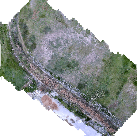
Fig. 1. Stitched map produced by the FastMosaic pipeline from survey imagery collected during a waypoint tour.
We built our own mosaicker rather than adopting an external photogrammetry suite because it keeps the mapping chain under end-to-end control inside the same Python toolchain as the rest of our software, adds no external processing dependency at the field station and produces the submission PNG directly. It also provides what batch photogrammetry tools do not: a real-time mode that consumes the A8 RTSP stream during the survey and builds an incremental preview, so a coverage gap costs a re-fly of one leg rather than a discovered too late hole in the submitted map.
Honest limits: FastMosaic output is a visual mosaic rather than a rigorously orthorectified product similarity transforms do not model perspective or terrain relief and incremental placement can accumulate drift over long chains so we control quality at the source: nadir gimbal imagery, an overlap-rich survey pattern and the maneuver gate, validated by side-by-side comparison against reference imagery of the same area. Camera intrinsics use nominal datasheet-derived values (f_x ≈ 1124 px) and lens distortion is currently uncorrected; a checkerboard calibration is the planned refinement once physical camera access allows.
III. Test Strategy
A. Overall Testing Strategy
Our testing strategy followed a structured and incremental verification process to validate the performance, reliability and integration of the UAV before competition deployment. Rather than evaluating the aircraft only after full assembly each subsystem was verified individually before progressing to system integration, simulation and field testing. This approach reduced development risks, simplified troubleshooting and ensured that each subsystem satisfied its operational requirements prior to autonomous flight. The overall validation process consisted of component
level testing, simulation-based verification, dataset evaluation for the onboard detection system, field testing and mapping validation. Mechanical, electrical, navigation, communication and payload subsystems were first tested independently followed by integrated simulations using Gazebo, SITL, ROS 2, ArduPilot and Mission Planner. Finally complete mission scenarios were verified through real flight tests to evaluate autonomous navigation, object detection, payload delivery and risk mapping under representative operating conditions.
B. Component-Level Testing
Component-level testing was conducted to verify the functionality, reliability and operational performance of each subsystem before full system integration. Each subsystem was evaluated independently under representative operating conditions to ensure compliance with mission requirements while minimizing integration risks during autonomous flight.
Propulsion System: The propulsion subsystem was tested to evaluate the performance of the motors, electronic speed controller (ESC) and power distribution system. ESC calibration was performed using Mission Planner in the ArduPilot environment to achieve consistent throttle response and synchronized motor operation. Battery voltage, current consumption and power distribution were monitored under different operating conditions to evaluate the stability of the electrical system.
Flight Controller:The Orange Cube Plus flight controller was configured and calibrated using Mission Planner. Accelerometer, gyroscope, compass and radio calibrations were completed before flight testing. Sensor outputs, flight modes and failsafe functions were then verified during pre-flight inspections to ensure correct operation before autonomous flights.
Navigation System:The Neo3 Pro GNSS receiver and CRTK 9Ps RTK module were tested outdoors to evaluate positioning accuracy and navigation performance. GPS signal acquisition, RTK correction reception and waypoint tracking were verified before autonomous flight operations.
Communication System: The HM30 digital transmission system was tested for telemetry communication, command transmission, and HD video streaming. MAVLink communication between the Ground Control Station and the flight controller was verified through Mission Planner by uploading test missions, monitoring telemetry data and confirming stable communication throughout the tests.
Airdrop System: The payload delivery subsystem was tested by operating the servo-actuated locking mechanisms and the motor-driven winch assemblies independently. Lock release, controlled payload descent, and bidirectional control of the HW-231 dual-channel H-bridge motor driver were verified for both delivery mechanisms. Repeated tests demonstrated consistent payload deployment and reliable operation of the system.
Electrical Safety Considerations: The electrical system was designed to ensure safe and reliable operation under expected flight conditions. High-current propulsion wiring was routed separately from avionics power and signal lines to reduce electromagnetic interference. In addition, a hardware kill switch was incorporated to allow immediate shutdown of the propulsion system during emergency situations. Wire sizes were selected according to the expected current of each subsystem to minimize voltage drop and prevent excessive heating under load.
C. Simulation-Based Testing
Every new capability was flown in simulation before it was flown on hardware. The environment brings together Gazebo, ArduPilot SITL (Software-in-the-Loop), ROS 2 and pymavlink, and reproduces the actual flight architecture rather than running as a single desktop application: the flight dynamics simulator, the Mission Planner ground station and the Jetson companion computer operate as separate nodes on a shared network (Fig. 2). Camera imagery reaches the Jetson over an RTSP stream, so the complete image-processing pipeline runs under conditions that closely match an actual flight. This approach cut development iteration time and limited the risk of damaging hardware during early testing.
Flight Path Simulation: SITL and Gazebo were used to simulate autonomous takeoff, waypoint navigation, landing and Return-to-Launch (RTL) scenarios. Mission planning and monitoring were performed using Mission Planner, while survey
missions were executed on waypoint grids generated with the Simple Grid tool. PID tuning
and GPS-lock logic were validated using a
simulation model configured with the weight and propeller characteristics of the actual platform (MN505), allowing flight-controller behavior to be verified before hardware testing.
Object Detection Testing: The Gazebo camera stream was delivered to the Jetson through RTSP so that the complete onboard detection pipeline could be evaluated on the target hardware. Simulated objects with known positions and orientations were introduced to assess detection accuracy, bounding-box alignment, processing latency and onboard positioning decisions under representative operating conditions.
Emergency Scenario Simulation: Failure cases including GPS/EKF degradation, communication loss with the Ground Control Station or Jetson and low-battery conditions were introduced using SITL. Automatic LOITER, landing and Return-to-Launch behaviors were verified through telemetry logs, while the distributed network architecture enabled realistic testing of communication latency and link interruptions. These simulations accelerated software development while reducing the risk of hardware damage during early flight testing.
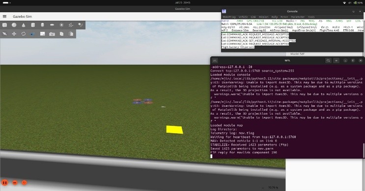
Fig. 2. Simulation environment during a test run: Gazebo world with the simulated vehicle, ArduPilot SITL and telemetry consoles operating as networked nodes.
D. Dataset-Level Testing
The retrained YOLO11m model was evaluated using a validation dataset consisting exclusively of real aerial DJI imagery containing 31 images and 121 labeled instances. The model achieved an overall mAP50 of 0.950 and mAP50-95 of 0.745, while precision and recall were evaluated according to standard object detection metrics. Performance was assessed separately for mannequin and tent classes to verify detection reliability under realistic aerial conditions. Precision P = TP/(TP+FP), recall R = TP/(TP+FN); mAP50 averages AP at IoU 0.5 across classes.
Table 1.
Class | P | R | mAP50 | Val instances | ||
|---|---|---|---|---|---|---|
mannequin | 0.902 | 0.801 | 0.906 | 115 | ||
tent | 0.942 | 1.000 | 0.995 | 6 | ||
All | — | — | 0.950 | 121 |
Although the tent class achieved excellent detection performance, the evaluation included only six validation instances. Therefore, these results are reported transparently without claiming statistical confidence beyond the available sample size. In addition, tiled inference was investigated as a proof of concept for small-object recovery. On two held-out aerial images where full-frame inference produced no detections, tiled inference recovered additional detections while maintaining acceptable processing performance on the Jetson Orin NX. These findings supported the selection of the full-frame flight configuration used during autonomous missions.
E. Field Testing
Field validation proceeded in two stages. Detection robustness was first evaluated under low-light conditions using human stand-ins positioned on concrete surfaces. Across six trials, the detection system consistently produced confidence values of approximately 0.75 from distances of 20–25 m despite environmental conditions differing from the primary training dataset. After this stage was passed, an end-to-end flight test was conducted to validate the complete autonomous mission pipeline under real operating conditions. During this test, both competition targets were detected from an altitude of approximately 20 m AGL, after which their positions were transferred to the guidance system and autonomous navigation proceeded to the designated release locations. Payload deployment was then performed at the same 20 m altitude: the beacon landed successfully on the tent target, while the water bottle landed approximately 5 m from the mannequin during this initial integrated flight test.
F. Mapping Testing
The mapping subsystem was verified through both component-level and mission-level evaluations. Prior to flight operations, RTSP video ingestion was validated using a dedicated bench-testing utility to ensure reliable communication with the SIYI A8 Mini camera. During map generation, frames captured during sharp heading changes were filtered automatically while images that failed feature matching were discarded instead of being forcefully integrated into the final mosaic preserving overall map quality.
The generated ortho mosaic was evaluated according to the SUAS mapping requirements. Acceptance criteria included complete coverage of the surveyed area, seamless image alignment without visible stitching artifacts, consistent exposure across the mosaic and visual comparison with reference imagery of the same region. These verification steps confirmed that the mapping pipeline produced competition-ready outputs suitable for autonomous mission planning and post-flight analysis.